
- Information
- Key Cutting Information
- Key Programming Information
- Customer Reviews (0)
Genuine Chrysler Grand Voyager 5 Button Fobik Remote Chrysler Part Numbers: 56046710AE / 56046710AF / 56046710AG 5 Buttons: Lock, Unlock, Boot, Left Door and Right Door Transponder: ID46 - PCF7941 Frequency: 433 Mhz Battery Type: CR2032 Key Blade: Y160 ISN:
Genuine Chrysler remote key supplied with the original manufacturer packaging.
This key comes complete with all electronics and can be supplied either blank (uncut) or cut to your vehicle. To find out more about our cutting service please see the ‘Key Cutting Information’ tab above.
Suitable for the following models (fitted with motorised rear door):
Chrysler Grand Voyager (2008 - 2013)
Dates are given as a guide only and we cannot take any responsibility for incorrect part compatibility. If you are unsure if this is the correct part for your vehicle please fill in our Parts Enquiry form and we will confirm the correct part number for you. IMPORTANT:
The key will need to be programmed before it will start the car and open and lock the doors remotely. Please see the 'Key Programming Information' tab above for guidance on who will be able to program this key type.
Trade Customers:
Customers who are in the locksmith or motor trade may register for a trade account. Trade account customers get preferential pricing and loyalty discounts. Please register using the link at the top of the page to find out more.
Keys Cut to Key Number
We can cut keys to the manufacturer's key number (often referred to as the 'key code'). For this particular blade the key number will usually be printed in the service book and will start with one letter followed by four numbers, e.g. M1234.
NOTE: The key number will not be on the key itself.
Keys Cut to Photo
If the option for 'Cut to Photo' is shown in the key cutting drop down box we can cut the key to a clear picture of the blade. The blade should ideally be on a white background with the end of the blade facing towards the right. The picture should not be blurred and the cuts of the key should be easily identifiable. You can see an example picture here .
Keys Cut to VIN (Chassis Number) - European Vehicles Only
We can cut the key to your VIN and supply you with the key code. To do this we require a copy of the inside page of the logbook / ownership document, detailing the vehicle's registration, VIN and vehicle owner's details. The vehicle owner's details must match the delivery address details when placing your order. Please scan or take a clear photo of the log book and upload it using the ‘upload a photo’ option.
IMPORTANT: Keys cut to VIN will be cut to the original locks of the vehicle. If the vehicle has previously had the locks changed then obviously this key will not work. Keys cut to VIN are non-refundable.
Important Information
The key will need to be programmed before it will start the car and open and lock the doors remotely. Please see the following guidance for who will be able to program this key type.
Who can program this key? Chrysler main dealer – Yes Independent garage – Yes Specialist auto electrician – Yes Professional vehicle locksmith – Yes
Programming Method: Immobiliser: Diagnostically Remote: Automatically with immobiliser
Be the first to Write a Review for this item!
Model: FK56046710AG Bar Code: CHR-R1 Brand: Chrysler

Genuine Chrysler Grand Voyager 5 Button Fobik Remote
Delivery: Surcharge of £5.00

Chrysler Equivalent Part Number: 56046710AG Frequency: 433 Mhz

Chrysler Equivalent Part Number: 68029829AB Profile: CY24
Home > Remote Keys > Chrysler Remote Keys

Your cart is empty
Note: Some key fobs may look the same, but they may have different frequencies, capabilities, or keyways. Pay attention when choosing the right replacement. If you don't see an exact match, contact us.
Have an existing fob?
Use the search filters below to sort products by Year, Make, and Model and compare Part Number and FCC ID with numbers on your key fob.
No existing key fob?
Contact Us with your vehicle VIN number , and we will help you find the correct replacement.
- Regular Remote
- Aftermarket New
- OEM Pre-owned
- OEM Refurbished
- Grand Voyager
Chrysler Grand Voyager Key Fobs
Showing 1 - 4 of 4 products

Welcome to our collection of Chrysler Grand Voyager key fobs, keyless entry remotes, and keys. Our collection includes high-quality replacement parts for your Chrysler Grand Voyager, designed to keep your vehicle running smoothly and safely.
The Chrysler Grand Voyager has been a favorite among families in the USA for many years. With its spacious interior, comfortable seating, and advanced entertainment systems, it's no wonder why this vehicle is such a popular choice for road trips and daily commutes alike. Whether you own a Chrysler Grand Voyager LX, Chrysler Grand Voyager Limited, or Chrysler Grand Voyager Touring, we have the key fobs, keyless entry remotes, and keys you need to keep your vehicle secure and on the road.
Our knowledgeable team of experts has carefully selected each item in our collection to ensure that it meets the highest standards of quality and performance. We understand that the safety and security of your vehicle is of utmost importance, which is why we offer only the best products on the market.
Don't let a broken or malfunctioning key fob, keyless entry remote, or key slow you down. Browse our collection today and find the perfect replacement part for your Chrysler Grand Voyager. With our fast shipping and excellent customer service, you can be confident that you're making the right choice for your vehicle.
Fast shipping
Same day handling! Choose from multiple USPS and UPS shipping methods.
Satisfaction Guaranteed
30 day no hassle returns and exchanges.
Top-notch Support
Our agents can walk you through programming and troubleshooting.
Security and Privacy
We use ssl security to protect your data. We won't ever sell your data.
- Opens in a new window.

Genuine Chrysler Grand Voyager Remote Key - 68060264AA
Model: F00K68060264AA Part Number: 68060264AA Brand: FCA
- Information
Product Availability
- Collection & Delivery
- Returns & Refunds
- Reviews (0)
Genuine Chrysler Grand Voyager Remote Key
Part Number: 68060264AA
Suitable for: Chrysler Grand Voyager (2005 - 2009)
You can see the stock status of the part under the ‘add to basket’ button.
Parts marked as ‘Availability: In Stock’ are available in our warehouse for same day shipping.
Parts marked as ‘Factory Order’ are available to order from the manufacturer but this will usually add an extra day (sometimes two) to the dispatch time. In some cases the manufacturer may not have stock in the UK. If this is the case the part may come from overseas which can add additional time to your order. If this applies to your order we will notify you before we place the order with the manufacturer.
Collection & Delivery
For business customers located in a 20 mile radius we normally deliver your parts via our trade parts van, usually same day if ordered in morning. Orders placed in the afternoon will be delivered on the next working day.
For domestic and business customers outside of our area, we have a daily courier collection for both express and economy services.
IMPORTANT NOTE FOR DELIVERY CHARGES:
Because of the way parts data is imported into the website there is sometimes missing weight or dimension information that may result in an incorrect shipping charge. For stocked items this should never be an issue but for special order factory items there occasionally may be additional shipping charges to pay. If this is the case we will always notify you immediately and you can choose to proceed or cancel the order without penalty.
Parts in stock can normally be collected from our parts department within 30 minutes of ordering.
Special order parts can be collected once they arrive from the manufacturer. We will notify you when the part is available for collection.
Some parts attract a surcharge which is refundable on return of your current part. Parts commonly affected by the surcharge are engines, gearboxes, electronic modules etc. We will try and notify you of this wherever possible prior to purchase but in some cases it may not be apparent until we order the part. If a part does attract a surcharge we will notify you immediately and you can decide to whether to continue or cancel the order.
The surcharge is normally refundable around 7 - 10 days after return of the old part in suitable condition.
Returns & Refunds
Standard Parts
All standard stocked parts can be returned for a full refund within 7 days of you receiving the product for any reason.
You must contact us in advance of returning a part to confirm the reason for return and any other information we require. Failure to do so will result in delays to your return being processed.
The part must be returned in perfect condition, exactly as packed by the manufacturer.
The part must be returned with the original box and any associated packaging to be eligible for return.
The buyer is responsible for all shipping costs.
Special Order Parts
Special order items that are not in the category of ‘Programmable Parts’ can be returned within 7 days of you receiving the product for a refund, but this will incur a 7.5% handling charge to cover the cost of return to the manufacturer. The handing charge is automatically deducted from the refund amount on return.
Special order items that are considered ‘ Programmable Parts ’ (keys, locks, modules, control units etc.) cannot be returned under any circumstances unless faulty. If the part is deemed to faulty it must be proven by the manufacturer's technical support service to be eligible for return. The procedure for this is complex so please contact us if you believe a programmable part is faulty and we will direct you accordingly.
Be the first to Write a Review for this item!

37145-55JV3-000

37145-53JV1-000

37145-55JC1-000

Home > Keys & Locksets > Remote Keys > Chrysler Remote Keys
- 1-888-511-3595
- Chrysler Parts
- Dodge Parts
- Accessories
- Login/Register
- Track Order
- Help Center
Genuine Chrysler Voyager Car Key
Enter your vehicle info to find more parts and verify fitment.
- Select Vehicle by VIN
- Select Vehicle by Model
20 Car Keys found

Chrysler Voyager Module-KEYLESS Entry Receiver
- Other Name : Module Keyless Entry Receiver; Control Module, Module, Receiver
- 2002-2003 Chrysler Voyager | Base, EC, LX | 4 Cyl 2.4L, 6 Cyl 3.3L

Chrysler Voyager TRANSMTR-Integrated Key Fob
- Other Name : Transmitter Integrated Key Fob
- Replaced by : 68217832AD
- 2020 Chrysler Voyager | L FWD, LX FWD, LXI FWD | 6 Cyl 3.6L

Chrysler Voyager Blank
- Replaces : 68289894AB, 68289894AA

Chrysler Voyager TRAMSMTR-KEYLESS Entry
- Other Name : Transmitter Keyless Entry
- Replaced by : 4686481AF
- 2001-2003 Chrysler Voyager | Base, EC, LX | 4 Cyl 2.4L, 6 Cyl 3.3L

Chrysler Voyager Key-Blank
- Other Name : Key Blank

- Replaced by : 5018869AD

- Other Name : Key Blank 84 Groove; Key
- 2000 Chrysler Voyager | Base, SE | 4 Cyl 2.4L, 6 Cyl 3.0L, 6 Cyl 3.3L, 6 Cyl 3.8L

- Replaced by : 68241531AD
- Replaces : 68241531AB
- Other Name : Transmitter Integrated Key Fob; Transmitter
- Replaced by : 68217827AD
- Replaces : 68217827AB
- Replaced by : 68241532AD
- Replaced by : 68217829AD
Chrysler Voyager TRANSMITR-Integrated Key Fob

Chrysler Voyager Valet
- Other Name : Key Valet
- 2001-2002 Chrysler Voyager | Base, EC, LX | 4 Cyl 2.4L, 6 Cyl 3.3L
Chrysler Voyager Fob-Integrated Key Fob
- Replaces : 68217833AB
Chrysler Voyager Key Fob-Integrated Key Fob
- Other Name : Transmitter
- Replaced by : 68419652AC

Chrysler Voyager Module
- Other Name : Module Keyless Entry Receiver
- 2001 Chrysler Voyager | Base, LX | 4 Cyl 2.4L, 6 Cyl 3.3L

Chrysler Voyager TRANSMTR-KEYLESS Entry
- Other Name : Transmitter Keyless Entry; Transmitter

Chrysler Voyager Key-Valet

- Replaced by : 4686473AB
Related Chrysler Voyager Parts

Browse by Year

- Chrysler Manuals
- Grand Voyager 2015
Chrysler Grand Voyager 2015 Manual
- page of 806 Go / 806
Table of Contents
- If You Need Assistance
- Maintenance Schedule
- Maintenance Schedules
- Fluids, Lubricants and Genuine Parts
- Fluid Capacities
- Vehicle Specifications
- Front Turn Signal Lamp
- Front Fog Lamp
- Quad Headlamps
- Replacement Bulbs
- Bulb Replacement
- Vehicle Storage
- Cleaning the Instrument Panel Cupholders
- Appearance Care and Protection from Corrosion
- Cooling System
- Replacement Parts
- Maintenance Procedures
- Dealer Service
- Onboard Diagnostic System — Obd II
- Engine Compartment — 3.6L
- Towing a Disabled Vehicle
- Shift Lever Override
- Tow Eye Usage
- Freeing a Stuck Vehicle
- Jump-Starting Procedure
- Road Tire Installation
- Securing the Compact Spare Tire
- Jacking Instructions
- Preparations for Jacking
- To Access Spare Tire Winch Drive Nut
- Wheel and Tire Torque Specifications
- If Your Engine Overheats
- Hazard Warning Flashers
- Recreational Towing
- Trailer Towing
- Adding Fuel
- Tire Rotation Recommendations
- Radial Ply Tires
- Tire Pressures for High Speed Operation
- Tires — General Information
- Tire Loading and Tire Pressure
- Tire Terminology and Definitions
- Tire Markings
- Electronic Brake Control System
- Brake System
- Parking Brake
- Power Steering
- Driving on Slippery Surfaces
- Driving through Water
- Key Ignition Park Interlock
- Brake/Transmission Shift Interlock System
- Automatic Transmission
- If Engine Fails to Start
- Extreme Cold Weather (below –20°F or −29°C)
- Keyless Enter-N-Go™ — if Equipped
- Normal Starting
- Starting Procedures
- Rear Automatic Temperature Control (Atc) — if Equipped
- Automatic Temperature Control (Atc) — if Equipped
- Rear Manual Climate Control — if Equipped
- Climate Controls
- Radio Operation and Mobile Phones
- CD/DVD/Blu-Ray™ Disc Maintenance
- Steering Wheel Audio Controls — if Equipped
- Unwired® Stereo Headphone Lifetime Limited Warranty
- System Information
- Replacing the Remote Control Batteries
- Blu-Ray™ Player Remote Control — if Equipped
- Important Notes for Dual Video Screen System
- Remote Control
- Dual Video Screen
- Getting Started
- Blu-Ray™ Disc Player
- Sound Systems
- Ipod®/Usb/Mp3 Control — if Equipped
- Compass/Temperature Display — if Equipped
- Instrument Cluster Descriptions
- Instrument Panel Features
- Sun Screens — if Equipped
- Roof Luggage Rack — if Equipped
- Rear Window Defroster
- Rear Window Features
- Console Features
- Power Sunroof — if Equipped
- Rear Courtesy/Reading Lights — if Equipped
- Rear Overhead Consoles — if Equipped
- Sunglass Storage (Non-Sunroof Only)
- Overhead Consoles
- Parkview® Rear Back up Camera — if Equipped
- Parksense® System Usage Precautions
- Service the Parksense® Rear Park Assist System
- Parksense® Rear Park Assist — if Equipped
- Adjustable Pedals — if Equipped
- Tilt/Telescoping Steering Column
- Electronic Speed Control — if Equipped
- Headlight Washer
- Windshield Washers
- Windshield Wiper and Washers
- Multifunction Lever
- Turn Signals
- Rear Fog Lights
- Headlight Leveling System — if Equipped
- Lights-On Reminder
- Headlights on with Wipers — if Equipped
- Easy Entry/Exit Seat (Available with Memory Seat Only)
- To Open and Close the Hood
- Memory Position Recall
- Driver Memory Seat — if Equipped
- Programming the Memory Feature
- Manually Folding Third Row Seats — if Equipped
- Third Row Power Folding Seat — if Equipped
- Third Row Power Recline — if Equipped
- Manual Reclining Seats — if Equipped
- Manual Front/Second Row Seat Adjuster
- Things You Should Know about Your Uconnect® Phone
- Advanced Phone Connectivity
- Uconnect® Phone Features
- Uconnect® Phone — if Equipped
- Illuminated Vanity Mirrors — if Equipped
- Driver's Outside Automatic Dimming Mirror — if Equipped
- Heated Mirrors — if Equipped
- Automatic Dimming Mirror — if Equipped
- Inside Day/Night Mirror — if Equipped
- Safety Checks You Should Make Inside the Vehicle
- Exhaust Gas
- Safety Tips
- Engine Break-In Recommendations
- Occupant Restraint Systems
- Sliding Side Door Child Protection Lock
- Power Sliding Side Door — if Equipped
- Sliding Side Door
- Keyless Enter-N-Go
- Remote Power Unlock on First Press — if Equipped
- Power Open/Close Power Liftgate — if Equipped
- Programming Additional Transmitters
- Illuminated Entry
- Remote Keyless Entry (Rke) — if Equipped
- Using the Keyless Entry Transmitter
- Vehicle Security Alarm — if Equipped
- Steering Wheel Lock — if Equipped
- To Manually Lock the Steering Wheel
- Removing Key Fob from Ignition
- A Word about Your Keys
- Vehicle Identification Number
- Warnings and Cautions
- How to Use this Manual
- Important Notice
Advertisement
Quick Links
- 1 Maintenance Schedule
- Download this manual
Related Manuals for Chrysler Grand Voyager 2015

Summary of Contents for Chrysler Grand Voyager 2015
- Page 1 Grand Voyager 1 5 Y 5 3 4 - 1 2 6 - A R A - A A...
- Page 387 é...
- Page 389 ñ ó...
- Page 390 ä...
- Page 391 ó...
- Page 392 é...
- Page 393 ų...
- Page 395 ú Ø...
- Page 396 ª é ż ń â ª ł ç...
- Page 400 ş ü ü ü ş...
- Page 422 Tongue Weight/Trailer Weight ..280 Transmitter, Remote Keyless Entry (RKE) . .17 Voice Command Torque Converter Clutch ...241 Transporting Pets ....68 Commands .
- Page 423 Reclining ....113 Cold Weather ....233 Tilt Steering Column ... . .139 Stow `n Go (Fold in Floor) .
- Page 424 Windows ....25 Programming Additional Key Fobs ..15 Energy Management Feature ..41 Power Steering Fluid ... . .341 Programming Additional Transmitters .
- Page 425 Loading Vehicle....159 Rearview ....79 Onboard Diagnostic System..312 Tires .
- Page 426 Instrument Panel Cover ...327 Lead Free Gasoline ... . .274 High Beam/Low Beam Select ..133 Instrument Panel Lens Cleaning ..328 Leaks, Fluid .
- Page 427 Maintenance ....278 Gauge ....175 Hazard Warning Flasher ...289 Replacement Parts .
- Page 428 Dipsticks Electronic Stability Control (ESC) ..248 Oil Synthetic ....315 Automatic Transmission ..325 Electronic Vehicle Information Center Overheating .
- Page 429 Capacities, Fluid ....339 How To Stow An Unused ALR Console, Overhead....146 Caps, Filler Seat Belt .
- Page 430 About Your Brakes ....245 Air Conditioning Controls ..215 Fluid Level Check ... .325 Adding Engine Coolant (Antifreeze) .
- Page 431 INDEX...
Page 432: If You Need Assistance
- Page 435 IF YOU NEED ASSISTANCE When you contact the distributor, please pro- vide all of the following information: The manufacturer’s distributors are vitally inter- • Your name, address and phone number. ested in your satisfaction with their products and services. If a servicing problem or other •...
- Page 438 URUGUAY VENEZUELA Services And Parts SEVEL Uruguay S. A. Chrysler de Venezuela LLC Zona Industrial II, Av. Norte-Sur 5 C/C Calle Este-Oeste Convenio 820 Avenida Pancho Pepe Croquer. Zona Industrial Norte C.C LD Center Local B-2 Montevideo, Uruguay Valencia, Estado Caraboro...
- Page 439 +380 44 201 6060 International Toll Number Tel: +39 02 444 12 045 Telefax: (0212) 275 0357 Fax: +380 44 206 8889 Chrysler Customer Service* Universal Toll Free Number Tel: 00 800 1692 1692 Local Toll Free Number Tel: 0800 1692169...
- Page 440 SWEDEN SWITZERLAND TAIWAN Chrysler Taiwan Co. , LTD. Jeep Customer Service* Jeep Customer Service* 13th Floor Union Enterprise Plaza Universal Toll Free Number Universal Toll Free Number Tel: 00 800 0 426 5337 Tel: 00 800 0 426 5337 1109 Min Sheng East Road, Section 3...
- Page 441 Tel: +421 2 593099 901 Fax: 01 5883 487 International Toll Number Tel: +39 02 444 12 045 Fax: +421 2 593099 911 Chrysler Customer Service* Universal Toll Free Number Tel: 00 800 1692 1692 Local Toll Free Number Tel: 900 1692 00...
- Page 442 REUNION ROMANIA RUSSIA COTRANS AUTOMOBILES AUTO ITALIA IMPEX SRL Chrysler Russia SAO 17 Bd du Chaudron, 97490 Sainte Clotilde Bd. Timisoara nr. 60/D Testovskaya street, 10 Tel: 0262920000 Bucuresti, ROMANIA 123317 Moscow, Fax: 0262488443 Tel: +40 (0)21.444.333.4 Tel +7(495)-745-26-36 Fax: +40 (0)21.444.2779 Fax +7(495)-745-26-37 www.autoitalia.ro...
- Page 443 PORTUGAL PUERTO RICO AND U.S. VIRGIN Fiat Auto Poland S.A. Chrysler Portugal S.A. ISLANDS Chrysler International Services, S.A. ul. M. Grażyńskiego 141, Qta. da Fonte – Edif. Dª Amélia Calle 1 lote 1 Suite 205, Metro Office Park 43-300 Bielsko-Biała Rua Victor Câmara, 2 1ªA...
- Page 444 PANAMA PARAGUAY PERU Automotora Autostar S. A. Garden Autolider S.A Divemotor S.A. Avenida Domingo Diaz, Via Tocumen, Frente a Av. República de Argentina esq. Facundo Av. Canada 1160, Urb. Sta. Catalina la Urbanizacion El Crisol Machain Lima, Peru Panamá, Panamá Asuncion, Paraguay Zip Code Lima 13 Tel.: +507 233 7222...
- Page 445 NETHERLANDS NEW ZEALAND NORWAY Chrysler New Zealand RSA BIL Jeep Customer Service* Private Bag 14907 Øvre Eikervei 77 Universal Toll Free Number Tel: 00 800 0 426 5337 Panmure New Zealand N-3048 Drammen Local Toll Free Number Tel: 09573 7800 Tel.: +47 32 21 88 00...
- Page 446 Mob.: +371 29498662 Fax +370 52 665951 International Toll Number Tel: +39 02 444 12 045 Fax: +371 67812313 [email protected] Chrysler Customer Service* SIA “Autobrava” Universal Toll Free Number G.Astras street 5, Tel: 00 800 1692 1692 LV-1084 Riga Local Toll Free Number Tel.: +371 67812312...
- Page 447 Fax: +36-1-458-3148 International Toll Number International Toll Number Tel: +39 02 444 12 045 Tel: +39 02 444 12 045 Chrysler Customer Service* Chrysler Customer Service* Universal Toll Free Number Universal Toll Free Number Tel: 00 800 1692 1692 Tel: 00 800 1692 1692...
- Page 448 GREECE GUATEMALA HONDURAS Chrysler Jeep Dodge Hellas Grupo Q del Guatemala Grupo Q de Honduras 240-242 Kifisias Avenue Km 16 carretera a El Salvador, condado Blvd.. Centro América frente a Plaza Miraflores, concepción 15231 Halandri Athens, Greece Tegucigalpa, Honduras Ciudad de Guatemala, Guatemala Tel.: +30 210 6700800...
- Page 449 Fax: 020 5477 485 International Toll Number International Toll Number Tel: +39 02 444 12 045 Tel: +39 02 444 12 045 Chrysler Customer Service* Chrysler Customer Service* Universal Toll Free Number Universal Toll Free Number Tel: 00 800 1692 1692...
- Page 450 ECUADOR EL SALVADOR ESTONIA Chrysler Jeep Automotriz del Ecuador Grupo Q del Salvador Silberauto AS Av. Juan Tanca Marengo km. 4.5 Ave. Las Amapolas (Autopista Sur) Järvevana tee 11 Guayaquil, Ecuador Blvd. Los Próceres y Avenida No. 1, Lomas de...
- Page 451 Tel: +420 2 24806 111 Fax: (809) 565-8774 International Toll Number Tel: +39 02 444 12 045 Fax: +420 2 24806 312 Chrysler Customer Service* Universal Toll Free Number Tel: 00 800 1692 1692 Local Toll Free Number Tel: 80 20 30 35...
- Page 452 COLOMBIA COSTA RICA CROATIA Chrysler Colombia S.A. AutoStar Autocommerce Hrvatska d.o.o. Avenida Calle 26 # 70A-25 La Uruca, frente al Banco Nacional Jablanska 80 Zip Code 110931 San José, Costa Rica 10 000 Zagreb Bogotá Colombia PO Box 705-1150 Tel: 00 385 1 3869 001 Tel: +57 1 745 5777 Tel.: (506) 295 - 0000...
- Page 453 BULGARIA CHILE CHINA BALKAN STAR Comercial Chrysler S.A. Chrysler Group (China) Sales Limited Resbarska Str. 5 Av. Americo Vespucio 1601, Quilicura No. 1509, Building# 63, Dongsanhuan Middle Road 1510 Sofia Santiago, Chile Beijing Tel.: 359 2 91988 Zip Code 101931-7, 367-V PR.
- Page 454 BELGIUM BOLIVIA BRAZIL Ovando & Cia S.A. Chrysler do Brasil Jeep Customer Service* Av. Cristobal de Mendoza (2do Anillo) y Canal Rua Funchal, 418 - 16º andar CJ 1601/1602, Universal Toll Free Number Isuto Vila Olímpia Tel: 00 800 0 426 5337...
- Page 455 AUSTRALIA AUSTRIA BALANCE OF THE CARIBBEAN Chrysler Australia Pty. Ltd. Interamericana Trading Corporation Jeep Customer Service* ACN 124 956 505 Warrens, St. Michael Universal Toll Free Number Tel: 00 800 0 426 5337 PO Box 23267, Docklands Victoria 3008 Barbados, West Indies Local Toll Free Number Ph.
- Page 456 IF YOU NEED ASSISTANCE When you contact the distributor please provide ARGENTINA all of the following information: Chrysler Argentina S.A The manufacturer distributors are vitally inter- • Your name, address and phone number. Boulevard Azucena Villaflor 435 ested in your satisfaction with their products •...
- Page 457 • SPAIN ........363 • SWEDEN ....... . .364 •...
- Page 458 • ESTONIA ........354 • FINLAND ........355 •...
- Page 459 IF YOU NEED CONSUMER ASSISTANCE • IF YOU NEED ASSISTANCE ..... .348 • ARGENTINA .......348 •...
Page 460: Maintenance Schedule
Page 461: maintenance schedules.
- Page 463 Chassis Component Fluid, Lubricant, or Genuine Part Automatic Transmission Use Only ATF+4® Automatic Transmission Fluid. Failure to use ATF+4® fluid may affect the function or performance of your transmission. We recommend MOPAR® ATF+4® Fluid. Brake Master Cylinder We recommend you use MOPAR® DOT 3 and SAE J1703. If DOT 3 brake fluid is not available, then DOT 4 is acceptable.
Page 464: Fluids, Lubricants And Genuine Parts
Page 465: fluid capacities, page 466: vehicle specifications, page 467: front turn signal lamp, page 468: quad headlamps, page 469: replacement bulbs, page 470: vehicle storage.
- Page 471 Cavity Cartridge Fuse Mini-Fuse Description Instrument Cluster, SIREN, Clock Module, Multi-Function Control Switch – – 20 Amp Yellow If Equipped – 20 Amp Yellow Trailer Tow – If Equipped Rear View Mirror, Instrument Cluster, Multi-Function Control Switch, Tire – 20 Amp Yellow Pressure Monitor, Glow Plug Module –...
- Page 472 Cavity Cartridge Fuse Mini-Fuse Description 30 Amp Pink – Front Wiper LO/HI 20 Amp Blue – Front/Rear Washer 25 Amp Clear – Sunroof Module – 15 Amp Blue Rear Center Brake Lamp/Brake Switch – 20 Amp Yellow Front Fog Lamps –...
- Page 473 The numbers inside the TIPM cover correspond to the following table. Cavity Cartridge Fuse Mini-Fuse Description 40 Amp Green – Power Folding Seat 30 Amp Pink – Power Liftgate Module 30 Amp Pink – Rear Door Module 25 Amp Clear –...
- Page 474 CAUTION! (Continued) • When replacing a blown fuse, it is impor- tant to use only a fuse having the correct amperage rating. The use of a fuse with a rating other than indicated may result in a dangerous electrical system overload. If a properly rated fuse continues to blow, it indicates a problem in the circuit that must be corrected.
Page 475: Cleaning The Instrument Panel Cupholders
- Page 476 Do not use abrasive cleaning components, sol- alcohol content or abrasive cleaners. If soap CAUTION! vents, steel wool or other aggressive material to is used, wipe clean with a clean damp rag. • Do not use volatile solvents for cleaning clean the lenses.
- Page 477 • Remove as much of the stain as possible by To remove heavy soil and/or excessive brake Cleaning Interior Trim dust, use MOPAR® Wheel Cleaner or equiva- blotting with a clean, dry towel. Interior trim should be cleaned starting with a lent or select a non-abrasive, non-acidic •...
- Page 478 • Avoid using abrasive compounds and power • If your vehicle is damaged due to a collision The most common causes are: buffing that may diminish the gloss or thin out or similar cause that destroys the paint and • Road salt, dirt and moisture accumulation. the paint finish.
Page 479: Appearance Care And Protection From Corrosion
- Page 480 Add enough fluid to bring the level up to the Automatic Transmission WARNING! (Continued) requirements described on the brake fluid res- • To avoid contamination from foreign matter Selection Of Lubricant ervoir. With disc brakes, fluid level can be It is important to use the proper transmission or moisture, use only new brake fluid or expected to fall as the brake pads wear.
- Page 481 • If frequent engine coolant (antifreeze) addi- Material Standard MS-12106 should be added Warranty Handbook” for the proper mainte- to the coolant bottle. Do not overfill. tions are required, the cooling system should nance intervals. be pressure tested for leaks. Points To Remember •...
- Page 482 OAT that engine coolant (antifreeze) will return to the ties to determine the disposal rules for your coolant that meets the requirements of Chrysler radiator from the coolant recovery tank. community. To prevent ingestion by animals or...
- Page 483 “Maintaining Your Vehicle” for further coolant (antifreeze) that meets the require- engine coolant (antifreeze) products. Do information. ments of Chrysler Material Standard MS-12106. not use additional rust inhibitors or antirust When adding engine coolant (antifreeze): products, as they may not be compatible •...
Page 484: Cooling System
- Page 485 ing the filter cover, make sure the retaining components to ensure proper function. When NOTE: performing other underhood services, the hood tabs fully engage the cover. Life expectancy of wiper blades varies de- latch, release mechanism and safety catch pending on geographical area and fre- should be cleaned and lubricated.
- Page 486 Environmental Protection Agency and is an 2. Push in on the sides of the glove compart- WARNING! ozone-saving product. However, the manufac- ment and lower the door. • Use only refrigerants and compressor lu- turer recommends that air conditioning service 3.
- Page 487 In unusual situations involving grossly malfunc- WARNING! CAUTION! tioning engine operation, a scorching odor may • Battery fluid is a corrosive acid solution • It is essential when replacing the cables on suggest severe and abnormal catalyst over- and can burn or even blind you. Do not the battery that the positive cable is at- heating.
- Page 488 Exhaust System WARNING! (Continued) CAUTION! (Continued) The best protection against carbon monoxide • Damage to the catalytic converter can poison you. To avoid breathing CO, refer to entry into the vehicle body is a properly main- “Safety Tips/Exhaust Gas” in “Things To result if your vehicle is not kept in proper tained engine exhaust system.
- Page 489 all operating temperatures. This engine oil im- Disposing Of Used Engine Oil And Oil Engine Air Cleaner Filter proves low temperature starting and vehicle fuel Filters Refer to the “Service and Warranty Handbook” economy. Care should be taken in disposing of used for the proper maintenance intervals.
Page 490: Engine Oil
Page 491: dealer service, page 492: onboard diagnostic system — obd ii, page 493: engine compartment — 3.6l.
- Page 494 • FUSES ........329 •...
- Page 495 MAINTAINING YOUR VEHICLE • ENGINE COMPARTMENT — 3.6L ....311 • ONBOARD DIAGNOSTIC SYSTEM — OBD II ... .312 •...
- Page 497 • The towing speed must not exceed 25 mph CAUTION! (Continued) (40 km/h). • Do not push or tow this vehicle with an- If the transmission is not operable, or the other vehicle as damage to the bumper vehicle must be towed faster than 25 mph fascia and transmission may result.
Page 498: Towing A Disabled Vehicle
Page 499: shift lever override, page 500: tow eye usage, page 501: freeing a stuck vehicle.
- Page 502 Connecting The Jumper Cables 3. Disconnect the positive (+) end of the jumper WARNING! (Continued) cable from the positive (+) post of the 1. Connect the positive (+) end of the jumper the battery to explode and could result in booster battery.
Page 503: Jump-Starting Procedure
- Page 504 3. Align the valve notch in the wheel cover with 7. After 25 miles (40 km) check the lug nut 5. After 25 miles (40 km) check the lug nut the valve stem on the wheel. Install the cover torque with a torque wrench to ensure that torque with a torque wrench to ensure that by hand, snapping the cover over the two lug all lug nuts are properly seated against the...
Page 505: Road Tire Installation
Page 506: securing the compact spare tire.
- Page 507 NOTE: surface and enough clearance is obtained to In some situations the jack may need to be install the compact spare tire. Minimum tire placed on its side in order to be pushed lift provides maximum stability. under the vehicle. Return the jack to its correct orientation once it is under the ve- WARNING! hicle.
- Page 508 2. There are two jack engagement locations on Front jack location is on the sill flange of the vehicle body and is located 6 in (150 mm) from each side of the vehicle body. These loca- door edge. tions are on the sill flange of the vehicle body.
Page 509: Jacking Instructions
Page 510: preparations for jacking.
- Page 511 Spare Tire Tools The tool pouch contains three pieces and can be assembled into a spare tire hook; to remove the compact spare tire/cover assembly from under the vehicle, or a Winch T-handle; to raise/lower the compact spare tire/cover assembly. Assembling The Spare Tire Hook Spare Tire And Cover A —...
- Page 512 Super Console 2. Open the front drawer to expose the storage Premium/Base/Cargo Center Console For vehicles equipped with the Super Console, Pull the Winch Cover assembly plug (if compartment. the spare tire winch assembly drive nut is equipped) to access the winch drive nut. 3.
Page 513: To Access Spare Tire Winch Drive Nut
Page 514: wheel and tire torque specifications, page 515: hazard warning flashers.
- Page 516 • TOW EYE USAGE .......304 • Front Tow Eye Installation ......305 •...
- Page 517 WHAT TO DO IN EMERGENCIES • HAZARD WARNING FLASHERS ....289 • IF YOUR ENGINE OVERHEATS ....289 •...
- Page 518 Recreational Towing — All Models CAUTION! Recreational towing is allowed ONLY if the front • DO NOT flat tow this vehicle. Damage to wheels are OFF the ground. This may be ac- the drivetrain will result. If this vehicle complished using a tow dolly or vehicle trailer. If using a tow dolly, follow this procedure: requires towing, make sure the drive wheels are OFF the ground.
Page 519: Recreational Towing
- Page 520 Thirteen - Pin Connector Details Thirteen - Pin Connector Details Function Wire Function Wire Color Color Right Rear Position, Brown Reserve for Future Allo- Red/ Side Marker Lights, and cation ³ Blue Rear Registration Plate Return for Contact (Pin) White Illumination Device.
- Page 521 Seven - Pin Connector Details WARNING! (Continued) • Towing any trailer will increase your stopping Wire Function Color distance. When towing you should allow for additional space between your vehicle and Right Rear Position, the vehicle in front of you. Failure to do so Side Marker Lights, could result in an accident.
- Page 522 • Trailer brakes are recommended for trailers vehicle. Refer to “Tires – General Informa- WARNING! (Continued) tion” in “Starting and Operating” for proper over 1,000 lbs (450 kg) and required for • Vehicles with trailers should not be parked tire inflation procedures. trailers in excess of 1,653 lbs (750 kg).
- Page 523 the vehicle and trailer. Failure to load trailers Towing Requirements WARNING! (Continued) heavier in front is the cause of many trailer To promote proper break-in of your new vehicle • Make certain that the load is secured in the accidents. drivetrain components the following guidelines trailer and that it will not shift during travel.
- Page 524 chassis rating. It should never be less than 4% WARNING! of the trailer load, and not less than 55 lbs Frontal Area It is important that you do not exceed the (25 kg). You must consider tongue load as part The frontal area is the maximum height multi- maximum front or rear GAWR.
Page 525: Trailer Towing
Page 526: adding fuel.
- Page 527 Cruising Range quirements are included in MOPAR® engine refueling for a period of at least 5 minutes. oils, and in equivalent oils meeting Chrysler Because E-85 fuel contains less energy per Observing these precautions will avoid possible Specification MS-6395. The manufacturer only...
- Page 528 This section only covers those subjects that are Ethanol Fuel (E-85) WARNING! (Continued) unique to these vehicles. Please refer to the E-85 is a mixture of approximately 85% fuel the engine running for more than a short other sections of this manual for information on ethanol and 15% unleaded gasoline.
- Page 529 Ethanol new blends provide a cleaner burning fuel and recommended. Using gasolines that have these some are referred to as “reformulated gasoline.” additives will help improve fuel economy, re- The manufacturer recommends that your ve- duce emissions, maintain vehicle hicle be operated on fuel containing no more The manufacturer supports these efforts toward performance.
- Page 530 the “SERVICE TPM SYSTEM” message will no Light spark knock at low engine speeds is not Poor quality gasoline can cause problems such longer be displayed as long as no system fault harmful to your engine. However, continued as hard starting, stalling and stumble. If you exists.
- Page 531 Vehicles With Compact Spare seconds and then remain on solid, and the wheel and tire assemblies (road tires) with tires EVIC will display a “SERVICE TPM SYS- not equipped with Tire Pressure Monitoring • The compact spare tire (if equipped) does TEM”...
- Page 532 • Jamming due to electronic devices or driving TPMS Low Pressure Warnings tale Light” will extinguish once the updated tire The “Tire Pressure Monitoring Telltale Light” will pressure(s) have been received. next to facilities emitting the same radio illuminate in the instrument cluster, and an frequencies as the TPMS sensors.
- Page 533 displayed and the “Tire Pressure Monitoring TPMS Deactivation — If Equipped vehicle for up to 20 minutes above 24 km/h. The Telltale Light” will turn on. The TPMS can be deactivated if replacing all TPMS will chime, the “TPM Telltale Light” will four wheel and tire assemblies (road tires) with flash on and off for 75 seconds and then turn off.
- Page 534 NOTE: mended cold tire placard pressure value (lo- turn off when the fault condition no longer cated on the placard label on the driver’s-side exists. A system fault can occur with any of the It is particularly important for you to check B-Pillar).
- Page 535 • Driving on a significantly under-inflated measured tire pressure is 30 psi (207 kPa), a CAUTION! (Continued) temperature drop to 20°F (-7°C) will decrease tire causes the tire to overheat and can cause sensor damage. Using aftermarket the tire pressure to approximately 26 psi (179 lead to tire failure.
- Page 536 Refer to the “Service and Warranty Handbook” pressure requirements found on the tire placard above recommended cold tire placard pressure. for the proper maintenance intervals. The rea- label located on the driver’s-side B-Pillar. Once the low tire pressure warning has been sons for any rapid or unusual wear should be illuminated, the tire pressure must be increased The tire pressure will vary with temperature by...
Page 537: Tire Rotation Recommendations
- Page 538 Keep dismounted tires in a cool, dry place with you ever replace a wheel, make sure that the WARNING! (Continued) as little exposure to light as possible. Protect wheel’s specifications match those of the origi- only the tire and wheel sizes with load tires from contact with oil, grease, and gasoline.
- Page 539 • Driving style. Tire Spinning When stuck in mud, sand, snow, or ice condi- • Tire pressure - Improper cold tire inflation tions, do not spin your vehicle’s wheels above pressures can cause uneven wear patterns 30 mph (48 km/h) or for longer than 30 seconds to develop across the tire tread.
- Page 540 letter “T” or “S” preceding the size designation. use spare tire affects vehicle handling. Since it WARNING! (Continued) Example: T145/80D18 103M. is not the same as your original equipment tire, which apply to your spare. Failure to do so replace (or repair) the original equipment tire T, S = Temporary Spare Tire could result in spare tire failure and loss of and reinstall on the vehicle at the first...
- Page 541 If you need snow tires, Run Flat Tires — If Equipped CAUTION! select tires equivalent in Run Flat tires allow you the capability to drive 50 Because of the reduced ground clearance, size and type to the origi- miles (80 km) at 50 mph (80 km/h) after a rapid do not take your vehicle through an auto- nal equipment tires.
Page 542: Radial Ply Tires
Page 543: tire pressures for high speed operation, page 544: tires — general information.
- Page 546 NOTE: 2. Determine the combined weight of the driver NOTE: Under a maximum loaded vehicle condition, and passengers that will be riding in your • If your vehicle will be towing a trailer, load gross axle weight ratings (GAWRs) for the vehicle.
Page 547: Tire Loading And Tire Pressure
Page 548: tire terminology and definitions.
- Page 549 Tire Identification Number (TIN) one side. Tires with white sidewalls will have the mounted on the vehicle. If the TIN is not found full TIN, including the date code, located on the on the outboard side, then you will find it on the The TIN may be found on one or both sides of white sidewall side of the tire.
- Page 550 EXAMPLE: H = Speed Symbol – A symbol indicating the range of speeds at which a tire can carry a load corresponding to its load index under certain operating conditions – The maximum speed corresponding to the speed symbol should only be achieved under specified operating conditions (i.e., tire pressure, vehicle loading, road conditions, and posted speed limits) Load Identification: Absence of the following load identification symbols on the sidewall of the tire indicates a Standard Load (SL) tire:...
- Page 551 Tire Sizing Chart EXAMPLE: Example Size Designation: P215/65R15XL 95H, 215/65R15 96H, LT235/85R16C, T145/80D18 103M, 31x10.5 R15 LT P = Passenger car tire size based on U.S. design standards, or ..blank..= Passenger car tire based on European design standards, or LT = Light truck tire based on U.S.
Page 552: Tire Markings
- Page 553 Disabling/Enabling HSA 7. Press the “ESC Off” switch (located in the WARNING! If you wish to turn on or off the HSA system, it lower switch bank below the climate con- • If you use a trailer brake controller with can be done using the Customer Program- trols) four times within 20 seconds.
- Page 554 normal; the sounds will stop when ESC and you may feel the brakes being applied to HSA Activation Criteria becomes inactive following the maneuver individual wheels to attempt to stop the trailer The following criteria must be met in order for that caused the ESC activation.
- Page 555 the vehicle is in deep snow, sand or gravel NOTE: than 30 mph (48 km/h), see your authorized conditions and more wheel spin than ESC dealer as soon as possible to have the problem To improve the vehicle’s traction when driv- would normally allow is required to gain traction.
- Page 556 Electronic Stability Control (ESC) ESC Operating Modes WARNING! The Electronic Stability Control (ESC) en- The Electronic Stability Control System hances directional control and stability of the The “ESC Off” switch is located in (ESC) cannot prevent the natural laws of vehicle under various driving conditions.
- Page 557 Traction Control System (TCS) road conditions, and do not switch off the ESC The BAS complements the ABS. Applying the or TCS. brakes very quickly results in the best BAS The Traction Control System (TCS) monitors assistance. To receive the benefit of the system, the amount of wheel spin of each of the driven you must apply continuous braking pressure wheels.
- Page 558 to the ON position and may stay on for as long WARNING! WARNING! (Continued) as four seconds. • The Anti-Lock Brake System contains so- • The capabilities of an ABS-equipped ve- If the “Anti-Lock Brake Warning Light” remains phisticated electronic equipment that may hicle must never be exploited in a reckless on or comes on while driving, it indicates that be susceptible to interference caused by...
Page 559: Electronic Brake Control System
Page 560: parking brake, page 561: power steering.
- Page 562 Flowing/Rising Water WARNING! CAUTION! (Continued) • Driving through standing water limits your • Determine the condition of the road or the WARNING! vehicle’s traction capabilities. Do not ex- path that is under water and if there are Do not drive on or across a road or path ceed 5 mph (8 km/h) when driving through any obstacles in the way before driving where water is flowing and/or rising (as in...
Page 563: Driving On Slippery Surfaces
- Page 564 NOTE: (fourth gear), the transmission will not shift To exit ERS mode, simply hold the shift lever to above fourth gear (except to prevent engine the right (+) until “D” is once again displayed in Even if the transmission can be reset, we overspeed), but will shift through the lower the instrument cluster.
- Page 565 ther information) to select a lower gear range. third gear regardless of which forward gear is CAUTION! Under these conditions, using a lower gear selected. PARK, REVERSE, and NEUTRAL will Towing the vehicle, coasting, or driving for range will improve performance and extend continue to operate.
- Page 566 The following indicators should be used to REVERSE (R) WARNING! (Continued) ensure that you have engaged the transmission This range is for moving the vehicle backward. • When leaving the vehicle, always make into the PARK position: Shift into REVERSE only after the vehicle has sure the ignition is in the OFF position, •...
- Page 567 the Electronic Range Select (ERS) shift control When parking on a level surface, you may shift WARNING! (Continued) (refer to “Electronic Range Select (ERS) Opera- the transmission into PARK first, and then apply • It is dangerous to shift out of PARK or tion”...
- Page 568 • The transmission will upshift sooner and position (engine running or not) and the brake electronics are self-calibrating; therefore, the pedal must be pressed. downshift later. first few shifts on a new vehicle may be some- what abrupt. This is a normal condition, and •...
Page 569: Key Ignition Park Interlock
Page 570: automatic transmission, page 571: if engine fails to start, page 572: keyless enter-n-go™ — if equipped, page 573: starting procedures.
- Page 574 • TRAILER TOWING ......279 • Common Towing Definitions ..... . .279 •...
- Page 575 • Life Of Tire .......265 • Replacement Tires ......266 •...
- Page 576 • POWER STEERING ......243 • Power Steering Fluid Check ..... . .243 •...
- Page 577 STARTING AND OPERATING • STARTING PROCEDURES ..... . .231 • Automatic Transmission ..... . .231 •...
- Page 578 Operating Tips Chart...
- Page 579 NOTE: Winter Operation Outside Air Intake In many temperature positions, the Bi-Level To ensure the best possible heater and de- Make sure the air intake, located directly in front froster performance, make sure the engine of the windshield, is free of obstructions such as mode is designed to provide cooler air out of cooling system is functioning properly and the leaves.
- Page 580 2. Rotate the Rear Blower, Rear Temperature (EVIC) — Customer-Programmable Fea- Rear Temperature Control tures” in this Section. To change the temperature in the rear of the and the Rear Mode Control knobs to suit vehicle, rotate the temperature knob counter- your comfort needs.
Page 581: Rear Automatic Temperature Control (Atc) — If Equipped
- Page 582 • To return to Front screen, push "REAR" Air Conditioning (A/C) Recirculation Control The Air Conditioning (A/C) button allows the button again, or it will revert to the Front operator to manually activate or deactivate the screen after six seconds. When outside air contains smoke, air conditioning system.
- Page 583 right from the lowest blower setting. Performing Automatic Temperature Control (ATC) NOTE: this function will cause the ATC to switch into Automatic Operation • It is not necessary to move the tempera- manual mode. 1. Push the AUTO button on the front ATC ture settings.
- Page 584 3. Left Front Seat Occupant Temperature 9. Front Defrost Button rear window defroster automatically turns off after approximately 10 minutes. Display Push and release to change the current setting, the indicator illuminates when ON. Performing 13. Rear Lock This display shows the temperature setting for this function will cause the ATC to switch into the left front seat occupant.
Page 585: Automatic Temperature Control (Atc) — If Equipped
Page 586: rear manual climate control — if equipped.
- Page 587 • The A/C can be deselected manually with- temporarily block out any outside odors, smoke, 12. Bi-Level Mode Button or dust, and to cool the interior rapidly upon out disturbing the mode control selection. Air is directed through the panel and initial start-up in very hot or humid weather.
- Page 588 5. Right Front Temperature Control help dry the windshield. To improve fuel CAUTION! economy, use these modes only when nec- Provides right front seat occupant with indepen- Failure to follow these cautions can cause essary. dent temperature control. Turn left for cooler or damage to the heating elements: right for warmer temperature settings.
Page 589: Climate Controls
Page 590: radio operation and mobile phones, page 591: steering wheel audio controls — if equipped.
- Page 592 ing Source Code, you expressly assume all risk COMMERCIAL USE OF A CONSUMER TO http://www.cinavia.com. To request additional and liability associated with downloading and (i) ENCODE VIDEO IN COMPLIANCE WITH information about Cinavia by mail, send a post- using the Source Code and complying with the THE VC-1 STANDARD ("VC-1 VIDEO") card with your mailing address to: Cinavia Con- user agreements that accompany each Source...
- Page 593 and then push the remote control’s Right and then push the remote control’s Right cursor button to select the next digit. Repeat cursor button to select the next digit. Repeat this digit selection sequence for all four digits. this digit selection sequence for all four digits. •...
- Page 594 • When the entire four-digit code is entered, lower numbers are designated for all audiences push the remote control’s ENTER/OK button. and higher numbers are designated for more If the language code is not valid, the numbers adult audiences. all change back to " ". If the digits are visible When a DVD-Video disc is loaded, its rating is after this step, then the language code is compared to the setting in the DVD player.
- Page 595 • To change the current directory, use the the display until a safe temperature is reached. All of the Language settings have a special remote control’s PROG UP and Down but- This shutdown is necessary to protect the optics "Other" setting to accommodate languages tons or Rewind/skip back and fast fwd/skip of the DVD/Blu-ray™...
- Page 596 • For multi-session CDs that contain only mul- • For Blu-ray™ files, only version 1.0 / 1.1 / 2.2 The recommended method for labeling record- tiple CD-Audio sessions, the player will re- able discs (CD-R, CD-RW, and DVD-R) is with a / 2.3 and 2.4 ID3 tag data (such as artist number the tracks so each track number is permanent marker.
- Page 597 • The Blu-Ray™ Player always uses the file • Maximum frame rate for progressive result in a lowered apparent volume level. If you extension to determine the video format, so source 30 frames per second increase the volume level to account for this DivX files must always end with the exten- •...
- Page 598 • DVD-Video discs (MPEG-2 video compres- control playback of the disc. Using the options Listening To Audio With The Screen you can activate or cancel Scan play and Ran- Closed sion) (see notes about DVD Region Codes) dom play. To listen to only audio portion of the channel •...
- Page 599 radio mode. When shared, the radio has priority Information Mode Display Numeric Keypad Menu over the VES™ or all radio modes (FM, AM). When the display for either Channel 1 or Chan- The VES™ has the ability to switch tuner (AM/ nel 2 shows DIRECT TUNE, pushing the re- FM), SEEK, SCAN, TUNE, and recall presets in mote control’s OK button activates a numeric...
Page 600: Unwired® Stereo Headphone Lifetime Limited Warranty
- Page 601 mately three minutes after the rear video mode. When the mode is in an audio only system is turned off. source (such as FM), the Mode Selection menu appears on screen. Changing The Audio Mode For Headphones 4. When the Mode Selection menu appears on 1.
Page 602: Replacing The Remote Control Batteries
- Page 603 / (Play/Pause) – Begin/resume or pause 17. OK – Push to select the highlighted option disc play. in a menu. 9. Four Colored Buttons – Push to access – Push to navigate menus. Blu-ray™ Disc features. – Push to navigate menus. 10.
Page 604: Blu-Ray™ Player Remote Control — If Equipped
- Page 605 Controls And Indicators – In radio modes, push to seek the next on a data disc, PROG Up selects the next tunable station. In disc modes, push and directory and PROG Down selects the pre- 1. Power – Turns the screen and wireless hold to fast forward through the current vious directory.
Page 606: Important Notes For Dual Video Screen System
- Page 607 lects the appropriate mode after the disc is Right buttons or by repeatedly pushing the touchscreen in the VES™ column. To exit recognized and starts playing the Blu-ray™ SOURCE button, then push OK on the Re- press the back arrow button at the top left of Disc.
- Page 608 upper corner will turn off the remote con- 2. While looking at Screen 1 or 2, highlight 3. Press the 1 or 2 button on the touchscreen trol screen functions. VES™ DISC by either pushing Up/Down/ and then the DISC button on the touch- Left/Right buttons or by repeatedly pushing screen in the VES™...
- Page 609 Play A DVD Using The Touchscreen 2. While looking at Screen 1 or 2, highlight 3. Press the 1 or 2 button on the touchscreen Radio DISC by either pushing Up/Down/Left/Right and then the DISC button on the touch- buttons or by repeatedly pushing the screen in the MEDIA column.
Page 610: Dual Video Screen
- Page 611 nized by the disc drive. If playback does not NOTE: begin automatically after the disc is inserted into • Due to the size of the content on a Blu- the Blu-ray™ Player push the play button. If ray™ Disc, the disc may not start playing playback does not begin automatically after the immediately.
Page 612: Getting Started
- Page 613 LIST button: The LIST button will display the top Play Mode CAUTION! (Continued) level menu of the iPod® or external USB de- When switched to BTSA mode, some audio • Placing items on the iPod® or external vice. devices can start playing music over the vehi- USB device, or connections to the iPod®...
- Page 614 • While a track is playing, push the INFO the iPod® or external USB device, or push During all List modes, the iPod® displays all button to see the associated metadata (artist, the VR button and say "Shuffle ON" or lists in “wrap-around”...
- Page 615 • The audio device can be controlled using the • Use the TUNE control knob to select the next Once the audio device is connected and syn- chronized to the vehicle’s iPod®/USB/MP3 con- radio buttons to Play, Browse, and List the or previous track.
Page 616: Sound Systems
- Page 617 been activated or the check-mark is removed NOTE: tem is activated and will only show a visual alert showing the system has been deactivated. in the outside mirrors. The Blind Spot Alert The seat will return to the memorized seat feature can be activated in “Blind Spot Alert location (if Recall Memory with Remote Key Keyless Enter-N-Go™...
- Page 618 Automatic High Beams — If Equipped tion, push and release the SELECT button until will remain active for up to 10 minutes after the When this feature is selected, the high beam a check-mark appears next to the setting, show- ignition switch is turned OFF.
- Page 619 Nav–Turn By Turn Auto Unlock Doors RKE Linked To Memory- If Equipped When this feature is selected the navigation When this feature is selected, all doors will When this feature is selected the memory seat, system utilizes voice commands, guiding you unlock when the vehicle is stopped and the mirror, and radio settings will return to the through the drive route mile by mile, turn-by-...
Page 620: Compass/Temperature Display — If Equipped
- Page 621 • Average Fuel Economy (AVG) 3. Without pushing the brake pedal, push the Tire BAR / Tire PSI ENGINE START/STOP button once to return Push and release the UP or DOWN button until • Distance To Empty (DTE) ”Tire BAR” or “Tire PSI:” displays highlighted in the ignition to the OFF/LOCK position.
- Page 622 • Engine Temperature Warning Light and stop the vehicle. Then, shift the transmis- uled oil change interval. The engine oil change sion into NEUTRAL and run the engine at idle or indicator system is duty-cycle based, which This light warns of an overheated en- faster until the light turns off.
- Page 623 • Windshield Washer Fluid Low Indicator • Electronic Throttle Control (ETC) Light Do not operate the vehicle until the cause is corrected. This light does not show how much This light will turn on to indicate the This light informs you of a problem oil is in the engine.
- Page 624 • Blind Spot System Off — This message is EVIC White Telltale Lights “Electronic Speed Control” in “Understanding displayed when the ignition is turned to ON to The Features Of Your Vehicle.” This area will show reconfigurable white caution indicate the Blind Spot System has been telltales.
- Page 625 • Five Second Stored Messages • Liftgate Ajar (chime will sound when vehicle Start Aborted - Door Ajar" and "Push Brake Pedal and Push Button to Start". starts moving) When the appropriate conditions occur, this • Low Tire Pressure • Five Second Unstored Messages type of message takes control of the main display area for five seconds and then returns to •...
- Page 626 The system allows the driver to select informa- DOWN Button Electronic Vehicle Information tion by pushing the following buttons mounted Center (EVIC) Displays Push and release the DOWN but- on the steering wheel: The EVIC display consists of three sections: ton to scroll downward through the main menus and sub-menus.
- Page 627 “Lights” in “Understanding The Features Of This system conveniently allows the driver to CAUTION! (Continued) Your Vehicle” for further information). select a variety of useful information by pushing tioner turned off until the pointer drops back the switches mounted on the steering wheel. into the normal range.
- Page 628 the brake fluid level in the master cylinder has event of an EBD failure, the Brake Warning chime will sound. After the bulb check or when dropped below a specified level. Light will turn on along with the ABS Light. driving, if the driver’s seat belt remains unbuck- Immediate repair to the ABS system is required.
Page 629: Things To Know Before Starting Your Vehicle
- Page 630 gine and automatic transmission control sys- ters at speeds greater than 48 km/h, see your WARNING! tems. The light will illuminate when the key is in authorized dealer as soon as possible to have A malfunctioning catalytic converter, as ref- the ON/RUN position, before engine start.
- Page 631 If the ABS light is on, the brake system should tire failure. Under-inflation also reduces fuel properly. Always check the TPMS malfunction be serviced as soon as possible to restore the efficiency and tire tread life, and may affect the telltale after replacing one or more tires or benefits of Anti-Lock brakes.
Page 632: Instrument Cluster Descriptions
- Page 633 INSTRUMENT CLUSTER...
Page 634: Instrument Panel Features
- Page 635 • Locking The Remote Control .....201 • Replacing The Remote Control Batteries ....202 •...
- Page 636 • Compass/Temperature Display — If Equipped ... . .184 • Customer-Programmable Features (System Setup) ..184 • SOUND SYSTEMS ......188 •...
- Page 637 UNDERSTANDING YOUR INSTRUMENT PANEL • INSTRUMENT PANEL FEATURES ....170 • INSTRUMENT CLUSTER ......171 •...
Page 638: Sun Screens — If Equipped
- Page 639 Stowing The Crossbars CAUTION! Reverse the procedure to stow the crossbars, • Check deployed crossbars frequently and again, taking care to keep hand clear of pivoting retighten thumb screws as necessary. joint. Crossbars are identical and can be stowed • To avoid damage to the roof rack and in either rail nest.
- Page 640 NOTE: The crossbars are identical and can be placed in any two of the three deploy positions. Loosening Crossbars Stowed Position CAUTION! Use care when removing and handling the crossbars to prevent damage to the vehicle. Deploy Positions – Choose Two Of Three Bend the crossbar supports at each end, taking Make sure the directional arrows on the cross- care to keep hand clear of pivoting joint.
Page 641: Roof Luggage Rack — If Equipped
Page 642: rear window features.
- Page 643 Dual Storage Bins 2. Slide the console forward into the floor Position 3 shows the top portion of the console bracket. in a rearward position. This is accomplished by 3. Rotate the rear of the console down until it is lifting the upper most latch at the front of the resting on the floor bracket.
- Page 644 • Large console center storage will store head- 5. Pull up on the console to be sure it is firmly phones for the available rear DVD entertain- latched. ment system or other items • 12 Volt DC power outlet provides continuous WARNING! power inside the console for cell phones or In an accident, serious injury could result if...
Page 645: Console Features
- Page 646 NOTE: CAUTION! In the event of an individual being locked The storage bin cover must be flat and inside the storage bin, the storage bin cover locked to avoid damage from contact with can be opened from inside of the bin by the front seat tracks, which have minimal pushing on the glow-in-the-dark lever at- clearance to the cover.
- Page 647 WARNING! WARNING! (Continued) • Do not allow children to have access to the In a collision, serious injury could result if the seat storage bin covers are not properly second row seat storage bins. Once in the latched. storage bin, young children may not be •...
- Page 648 Door Trim Panel Storage Front Door Storage Both interior front door panels have multiple pockets for storage. WARNING! If containers of hot liquid are placed in the bottle holder, they can spill when the door is closed, burning the occupants. Be careful when closing the doors to avoid injury.
- Page 649 Pull upward on the ash receiver to remove for Upper Glove Compartment cleaning and/or storage. To open the upper compartment, press in on the button, located on the left side of the upper The left rear trim panel cupholder is designed to door.
- Page 650 Rear Cupholders Premium Console Cupholders Interior Bottle Holder Premium Console Cupholders — If Interior Bottle Holders Two outboard mesh pockets are on intermedi- ate seating. The mesh pockets are flexible Equipped There are four bottle holders located in the enough to hold juice boxes, toys, games or MP3 interior.
- Page 651 Instrument Panel Cupholders Super Console — If Equipped CAUTION! (Continued) The instrument panel cupholders are located in On models equipped with the Super Console, • After the use of high power draw accesso- a pull-out drawer just above the lower storage there are two cupholders located in the center ries, or long periods of the vehicle not bin.
- Page 652 WARNING! (Continued) • Do not touch with wet hands. • Close the lid when not in use and while driving the vehicle. • If this outlet is mishandled, it may cause an electric shock and failure. CAUTION! • Many accessories that can be plugged in Power Outlet Locations Underhood Fuse Box draw power from the vehicle’s battery,...
- Page 653 passenger-side power outlet is connected di- CAUTION! rectly to the battery. The driver-side power • Do not exceed the maximum power of 160 outlet will also operate a conventional cigar Watts (13 Amps) at 12 Volts. If the 160 lighter unit (if equipped with an optional Smok- er’s Package).
- Page 654 Closing Sunroof — Manual Mode ing Express Vent operation, any movement of Sunroof Maintenance the switch will stop the sunroof. To close the sunroof, press and hold the switch Use only a non-abrasive cleaner and a soft in the forward position. Any release of the cloth to clean the glass panel.
Page 655: Power Sunroof — If Equipped
Page 656: rear courtesy/reading lights — if equipped, page 657: sunglass storage (non-sunroof only), page 658: overhead consoles, page 659: parkview® rear back up camera — if equipped.
- Page 660 • Jackhammers, large trucks, and other vi- vide a false indication that an obstacle is CAUTION! (Continued) brations could affect the performance of behind the fascia/bumper. • The vehicle must be driven slowly when ParkSense®. • Ensure the ParkSense® system is OFF if using ParkSense®...
Page 661: Service The Parksense® Rear Park Assist System
- Page 662 Slow Tone Fast Tone Continuous Tone The vehicle is close to the obstacle when the EVIC display shows one flashing arc and sounds a continuous tone. The following chart shows the warning alert operation when the system is detecting an obstacle: WARNING ALERTS Rear Distance Greater than...
- Page 663 the Customer-Programmable Features section ParkSense® Display of the Electronic Vehicle Information Center When the vehicle is in REVERSE, the warning (EVIC). Refer to “Electronic Vehicle Information display will turn ON indicating the system sta- Center (EVIC)/Personal Settings (Customer- tus. Programmable Features)” in “Understanding Your Instrument Panel”...
Page 664: Parksense® Rear Park Assist — If Equipped
Page 665: tilt/telescoping steering column.
- Page 666 • If the button is continually pressed, the set U.S. Speed (mph) Using Electronic Speed Control On Hills speed will continue to increase until the but- The transmission may downshift on hills to • Pressing the SET (-) button once will result in ton is released, then the new set speed will maintain the vehicle set speed.
- Page 667 NOTE: To Resume Speed WARNING! (Continued) In order to ensure proper operation, the To resume a previously set speed, push the control and have an accident. Always leave Electronic Speed Control System has been RES (+) button and release. Resume can be the system OFF when you are not using it.
Page 668: Headlight Washer
Page 669: windshield washers, page 670: windshield wiper and washers.
- Page 671 High/Low Beam Switch will cause headlights to remain on longer 2. Rotate the headlight switch counterclock- (closer to the vehicle). Also, dirt, film and When the headlights are turned on, pushing the wise to the AUTO (A) position. other obstructions on the windshield or multifunction lever toward the instrument panel 3.
Page 672: Multifunction Lever
Page 673: rear fog lights, page 674: headlight leveling system — if equipped, page 675: headlights on with wipers — if equipped.
- Page 676 2. Move to the front of the vehicle and look LIGHTS CAUTION! inside the center of the hood opening. Lo- To prevent possible damage, do not slam the Headlight Switch cate, then push the safety catch lever down- hood to close it. Lower the hood until it is ward while raising the hood at the same The headlight switch is located on the left side open approximately 6 in (15 cm), and then...
Page 677: To Open And Close The Hood
Page 678: memory position recall, page 679: driver memory seat — if equipped.
- Page 680 4. Pull release strap marked “3” to release the To Unfold Third Row Seats anchors. 1. Pull up on the assist strap to lift the seat out of the storage bin and push the seat forward until the anchors latch. 2.
Page 681: Manually Folding Third Row Seats — If Equipped
Page 682: third row power recline — if equipped.
- Page 683 Easy Entry For passengers seated in the third row, there is Removal The Quad seats can be tilted forward for easy a pull strap located on the outboard side of the The Quad seats can be removed if additional entry into the third row. With the Quad seat in seat near the bottom of the seat back.
- Page 684 position. Then, using body pressure, move for- Fold-Flat ward and rearward on the seat to be sure that To fold the seat, lift the recliner lever to the full the seat adjusters have latched. upward position and push the seatback forward until it rests on the seat cushion.
- Page 685 3. Pull up on the seatback recliner lever on the WARNING! outboard side of the seat to fold head rest In the event of a collision you could be and seatback and tumble seat forward. injured if the seat is not fully latched. Easy Entry Second Row The second row Stow ’n Go®...
- Page 686 7. Close the storage bin cover. To Unstow Second Row Seats WARNING! (Continued) 1. Pull up on the storage bin latch to open the • Sitting in a seat with the head restraint in CAUTION! cover. its lowered position could result in serious The storage bin cover must be locked and injury or death in a collision.
- Page 687 Seatback Recliner Lever, Seat Tumble, And Non-Adjustable Head Restraint Tumbled Second Row Seat Head Restraint Fold Lever 6. Push the seat into the storage bin. The non-adjustable head restraint and seatback will fold automatically during the seat tumble. No additional actuation is necessary. Automatic Folding Seatback Seat In Storage Bin The seat will automatically tumble into position...
- Page 688 Stow ’n Go® Seating — If Equipped On vehicles equipped with Stow ’n Go® seat- ing, the second and third row seats can be folded into the floor for convenient storage. Second Row Stow ’n Go® On vehicles equipped with Stow ’n Go® seats, the seats will fold and tumble in one motion.
- Page 689 NOTE: WARNING! (Continued) • The head restraints should only be re- • Active Head Restraints may be deployed if moved by qualified technicians, for ser- they are struck by an object such as a vice purposes only. If either of the head hand, foot or loose cargo.
- Page 690 Active Head Restraints — Front Seats WARNING! (Continued) Active Head Restraints are passive, deployable your chest. In a collision you could slide components, and vehicles with this equipment under the seat belt, which could result in cannot be readily identified by any markings, serious injury or death.
Page 691: Manual Reclining Seats — If Equipped
Page 692: manual front/second row seat adjuster.
- Page 693 CAUTION! WARNING! (Continued) Do not place any article under a power seat seat heater. It may cause burns even at or impede its ability to move as it may cause low temperatures, especially if used for damage to the seat controls. Seat travel may long periods of time.
- Page 694 Adjusting The Seat Forward Or Rearward direction of the switch. Release the switch when WARNING! The seat can be adjusted both forward and the desired position is reached. • Adjusting a seat while driving may be danger- rearward. Push the seat switch forward or rear- ous.
- Page 695 NOTE: off. This procedure may be repeated with a Power Seats — If Equipped new user. The system will adapt to the last Keep in mind that you have to push the Some models may be equipped with eight-way trained voice only. power seats for the driver and front passenger.
- Page 696 Disc Mode Memo Mode System Setup To switch to the disc mode, say “Disc.” In this To switch to the voice recorder mode, say To switch to system setup, you may say one of mode, you may say the following commands: “Memo.”...
- Page 697 The system will best recognize your speech if 3. Use the ON/OFF VOLUME rotary knob to Radio AM (Or Radio Long Wave Or Radio the windows are closed, and the heater/air Medium Wave — If Equipped) adjust the volume to a comfortable level conditioning blower control is set to low.
- Page 698 NOTE: NOTE: Primary Alternate (s) Take care to speak into the Voice Interface If you do not say a command within a few send System as calmly and normally as possible. seconds, the system will present you with a set up phone settings or The ability of the Voice Interface System to list of options.
- Page 699 Voice Commands Primary Alternate (s) Primary Alternate (s) Primary Alternate (s) cancel Italian Italiano zero confirmation confirmation language prompts list names continue list phones delete three main menu return to main menu dial four mobile download five mute Dutch Nederlands mute off edit seven...
- Page 703 Turn Voice Text Reply Incoming Announce- Bluetooth® Communication Link ment ON/OFF Mobile phones have been found to lose connec- tion to the Uconnect® Phone. When this hap- Turning the Voice Text Reply Incoming An- pens, the connection can generally be reestab- nouncement OFF will stop the system from lished by switching the phone off/on.
- Page 704 In a convertible vehicle, system performance After reading a message, you can “Reply” or 4. I need more direction. may be compromised with the convertible top “Forward” the message using Uconnect® 5. L O L. down. Phone. 6. Why? Recent Calls Send Messages: If your phone supports “Automatic Phonebook 7.
- Page 705 • Fully Closed Windows. 2. After the “Ready” prompt and the following Even though international dialing for most num- ber combinations is supported, some shortcut beep, say “Setup,” then “Reset.” • Dry Weather Condition. dialing number combinations may not be sup- •...
Page 706: Things You Should Know About Your Uconnect® Phone
Page 707: advanced phone connectivity.
- Page 708 You can also send stored Uconnect® Phone- Barge In — Overriding Prompts Phone And Network Status Indicators book entries as tones for fast and easy access The “Voice Command” button can be used If available on the radio and/or on a premium to voice mail and pager entries.
- Page 709 NOTE: 2. After the “Ready” prompt and the following This method is used in instances where one generally has to push numbers on the mobile beep, say “Breakdown service.” • The default number is 112. The number phone keypad while navigating through an au- dialed may not be applicable with the NOTE: tomated telephone system.
Page 710: Uconnect® Phone Features
- Page 711 • To bring the call back from hold, push and NOTE: phone call, as described under “Making a hold the Phone button until you hear a The Uconnect® Phone compatible phones Second Call While Current Call in Progress.” single beep. in the market today do not support rejecting 2.
- Page 712 2. After the “Ready” prompt and the following 3. To call one of the names in the list, push the Answer Or Reject An Incoming Call — No Call Currently In Progress beep, say “Phonebook Erase All.” Voice Command button during the When you receive a call on your mobile phone, •...
- Page 713 Edit Uconnect® Phonebook Entries “Phonebook Edit” can be used to add another wish to delete or you can say “List Names” to phone number to a name entry that already hear a list of the entries in the phonebook NOTE: exists in the phonebook.
- Page 714 • This downloaded phonebook cannot be ed- Bluetooth® Phones with Phone Book Access 4. When prompted, enter the number designa- Profile may support this feature. ited or deleted on the Uconnect® Phone. tion (e.g., “Home”, “Work”, “Mobile”, or These can only be edited on the mobile •...
- Page 715 4. When prompted, after the beep, say “Pair a vehicle, the Uconnect® Phone will use the 2. After the “Ready” prompt and the following priority 3 mobile phone when you make a Phone” and follow the audible prompts. beep, say “Call.” call.
- Page 716 mands are required after most Uconnect® in a normal conversational tone, as if speak- Pair (Link) Uconnect® Phone To A Mobile Phone prompts. You will be prompted for a ing to someone sitting a few feet/meters Phone specific command and then guided through the away from you.
- Page 717 Uconnect® Phone features Bluetooth® technol- Uconnect® Phone Button Uconnect® Phone can be adjusted either from ogy - the global standard that enables different the radio volume control knob or from the The radio or steering wheel con- electronic devices to connect to each other steering wheel radio control, if so equipped.
Page 718: Uconnect® Phone — If Equipped
- Page 719 When RCP is on and the vehicle is in RE- WARNING! VERSE, the driver is alerted using both the The Blind Spot Monitoring system is only an visual and audible alarms, including reducing aid to help detect objects in the blind spot the radio volume.
- Page 720 Overtaking/Approaching Overtaking/Passing Stationary Objects The BSM system is designed not to issue an The BSM system will not alert you of objects alert on stationary objects such as guardrails, that are traveling in the opposite direction of the posts, walls, foliage, berms, etc. However, oc- vehicle in adjacent lanes.
- Page 721 NOTE: addition to sounding an audible (chime) alert Entering From The Rear and reducing the radio volume. Refer to “Modes • The BSM system does NOT alert the Vehicles that come up from behind your vehicle Of Operation” for further information. on either side and enter the rear detection zone driver about rapidly approaching vehicles The BSM system monitors the detection zone...
Page 722: Illuminated Vanity Mirrors — If Equipped
- Page 723 Tilt Mirrors In Reverse (Available Power Folding Mirrors — If If the mirrors are in the folded position, and vehicle speed is equal or greater than 10 mph With Memory Seat Only) — If Equipped (16 km/h), they will automatically unfold. Equipped The switch for the power folding mirrors is located between the power mirror switches L...
Page 724: Driver's Outside Automatic Dimming Mirror — If Equipped
Page 725: automatic dimming mirror — if equipped.
- Page 726 • CONSOLE FEATURES ......159 • Basic Console ....... .159 •...
- Page 727 • Closing Sunroof — Express..... .149 • Closing Sunroof — Manual Mode ....150 •...
- Page 728 • ELECTRONIC SPEED CONTROL — IF EQUIPPED ...136 • To Activate ........137 •...
- Page 729 • TO OPEN AND CLOSE THE HOOD ....127 • LIGHTS ........128 •...
- Page 730 • Phone Call Features ......92 • Uconnect® Phone Features ......94 •...
Page 731: Understanding The Features Of Your Vehicle
- Page 733 Periodic Safety Checks You Should Door Latches WARNING! (Continued) Check for positive closing, latching, and locking. Make Outside The Vehicle • Always make sure that objects cannot fall Fluid Leaks Tires into the driver footwell while the vehicle is Check area under vehicle after overnight park- Examine tires for excessive tread wear and moving.
Page 734: Safety Checks You Should Make Inside The Vehicle
Page 735: safety tips, page 736: engine break-in recommendations.
- Page 737 2. Next, pull enough of the seat belt webbing Any seat belt system will loosen with time, so the seat forward to provide better access to check the belt occasionally, and pull it tight if from the retractor to pass it through the belt the tether anchorage.
- Page 738 Installing A Child Restraint With A 5. To lock the seat belt, pull down on the the Top Tether Anchorage” for directions to Switchable Automatic Locking Retractor shoulder part of the seat belt until you have attach a tether anchor. (ALR) pulled all the seat belt webbing out of the 9.
- Page 739 Lap/Shoulder Belt Systems What is the weight limit (child’s weight + weight Always use the tether anchor when using the of the child restraint) for using the Tether Anchor seat belt to install a forward facing child re- Weight limit of the Child Restraint with the seat belt to attach a forward facing child straint, up to the recommended weight limit of restraint?
- Page 740 the vehicle that the seat belts are not toys and Installing Child Restraints Using The Lap/Shoulder Belt Systems For Installing that they should not play with them. Vehicle Seat Belt Child Restraints In This Vehicle The seat belts in the rear passenger seating positions are equipped with either a Switchable WARNING! Automatic Locking Retractor (ALR) or a cinch-...
- Page 741 Center Seat LATCH 1. Loosen the adjusters on the lower straps 5. Tighten all of the straps as you push the child If a child restraint installed in the center position and on the tether strap of the child seat so restraint rearward and downward into the blocks the seat belt webbing or buckle for the that you can more easily attach the hooks or...
- Page 742 Locating the LATCH Anchorages The lower anchorages are round bars that are found at the rear of the seat cushion where it meets the seatback. They are just visible when you lean into the rear seat to install the child restraint. You will easily feel them if you run your finger along the gap between the seatback and seat cushion.
- Page 743 Child Restraint LATCH Positions Use the LATCH anchorage system until the combined weight What is the weight limit (child’s weight + weight of the child of the child and the child restraint is 65 lbs (29.5 kg). Use the restraint) for using the LATCH anchorage system to attach 65 lbs (29.5 kg) seat belt and tether anchor instead of the LATCH system the child restraint?
- Page 744 Lower Anchors And Tethers For Children used with the top tether anchorage to install the (LATCH) Restraint System child restraint. Please see the following table for more information. LATCH Positions For Installing Child Restraints In This Vehicle Second Row Bench •...
- Page 745 Recommendations For Attaching Child Restraints Restraint Type Combined Weight Use any attachment method shown with an “X” Below of the Child + Child LATCH – Lower An- Seat Belt Only LATCH – Lower An- Seat Belt + Top Restraint chors Only chors + Top Tether Tether Anchor Anchor...
- Page 746 Children Too Large For Booster Seats If the answer to any of these questions was WARNING! (Continued) Children who are large enough to wear the “no,” then the child still needs to use a booster • After a child restraint is installed in the shoulder belt comfortably, and whose legs are seat in this vehicle.
- Page 747 Infants And Child Restraints All children whose weight or height is above the WARNING! Safety experts recommend that children ride forward-facing limit for the child seat should use • Never place a rear-facing child restraint in rear-facing in the vehicle until they are two a belt-positioning booster seat until the vehicle’s front of an air bag.
- Page 748 child. Carefully read and follow all the instruc- tions and warnings in the child restraint Owner’s Manual and on all the labels attached to the child restraint. Before buying any restraint system, make sure that it has a label certifying that it meets all applicable Safety Standards.
- Page 749 Event Data Recorder (EDR) NOTE: Child Restraints This vehicle is equipped with an event data EDR data are recorded by your vehicle only Everyone in your vehicle needs to be buckled recorder (EDR). The main purpose of an EDR is up at all times, including babies and children.
- Page 750 • The Air Bag Warning Light does not come on WARNING! (Continued) WARNING! (Continued) during the four to eight seconds when the • It is dangerous to try to repair any part of the ignition is first turned on, stays on after ignition switch is first turned to the ON/RUN you start the vehicle, or if it comes on as you the air bag system yourself.
- Page 751 • Flash hazard lights as long as the battery has position or in the ACC position, the air bag WARNING! (Continued) power or until the ignition switch is turned to system is not on and the air bags will not inflate. Have the air bags, seat belt pretensioners, the “OFF”...
- Page 752 impact deploys the left Side Air Bags only and a belt pretensioners as well as the SABs and you haven’t healed significantly within a few right side impact deploys the right Side Air Bags SABICs on both sides of the vehicle. The roll- days, or if you have any blistering, see your only.
- Page 753 never lean on or sleep against the door, side WARNING! (Continued) WARNING! (Continued) windows, or area where the Side Air Bags • Relying on the Side Air Bags alone could vehicle which could alter the roof. Do not inflate, even if they are in an infant or child add an aftermarket sunroof to your vehicle.
- Page 754 Children are at an even greater risk of injury and seated properly, or if items are positioned in from a deploying air bag. the area where the SABICs inflate. Children are at an even greater risk of injury from a deploying air bag.
- Page 755 example, some pole collisions, truck underrides, blink your eyes. The air bags then quickly and angle offset collisions. deflate while helping to restrain the driver and front passenger. On the other hand, depending on the type and location of impact, Advanced Front Air Bags Knee Impact Bolsters may deploy in crashes with little vehicle front- The Knee Impact Bolsters help protect the...
- Page 756 may receive information from the front impact WARNING! WARNING! (Continued) sensors or other system components. • Being too close to the steering wheel or • Do not put anything on or around the air The first stage inflator is triggered immediately instrument panel during Advanced Front bag covers or attempt to open them manu- during an impact that requires air bag deploy-...
- Page 757 Supplemental Restraint System the center of the steering wheel. The passen- WARNING! (Continued) ger’s Advanced Front Air Bag is mounted in the (SRS) • Do not attempt to modify any part of your instrument panel, above the glove compart- Air Bag System Components Active Hood system.
- Page 758 reset position is intended to improve forward WARNING! driving visibility over the hood until the vehicle • Ignoring the Air Bag Warning Light in your can be serviced. instrument panel or the “SERVICE AC- The temporary hood reset position will leave the TIVE HOOD”...
- Page 759 4. The AHR front soft foam and trim half should hood upon an impact with a pedestrian or other Service Active Hood System object. The system is automatically activated lock into the back decorative plastic half. If the system has deployed the Active Hood, or when the vehicle is moving within a specified if it detects a malfunction in any part of the vehicle speed range.
- Page 760 NOTE: For more information on properly adjusting and positioning the head restraint, refer to “Adjusting Active Head Restraints” in “Un- derstanding The Features Of Your Vehicle.” Resetting Active Head Restraints (AHR) If the Active Head Restraints are triggered in a collision, you must reset the head restraint on the driver’s and front passenger’s seat before driving.
- Page 761 straint. The head restraint will be split in two WARNING! halves, with the front half being soft foam and • The seat belt assembly must be replaced if trim, the back half being decorative plastic. the switchable Automatic Locking Retrac- How The Active Head Restraints (AHR) Work tor (ALR) feature or any other seat belt The Occupant Restraint Controller (ORC) de-...
- Page 762 essary to comfortably wrap around the occu- How To Engage The Automatic Locking pant’s mid-section. Slide the latch plate into the Mode buckle until you hear a "click." 1. Buckle the combination lap and shoulder In Automatic Locking Mode, the shoulder belt is belt.
- Page 763 lease button. To verify the shoulder belt NOTE: Automatic Locking Retractor (ALR) — If Equipped anchorage is latched, pull downward on the These devices are not a substitute for The seat belts in the rear passenger seating shoulder belt anchorage until it is locked proper seat belt placement by the occupant.
- Page 764 6. When the seat belt is long enough to fit, allow the seat belt to retract fully. Insert the insert the latch plate into the buckle until you mini-latch plate and regular latch plate into hear a “click.” its stowed position. 7.
- Page 765 Mini-Latch And Buckle Connected Rear Center Seat Belt Buckled Detaching Mini-Latch And Buckle 2. Grasp the mini-latch plate and pull the seat belt over the seat. 3. Route the shoulder belt to the inside of the left head restraint. 4. When the seat belt is long enough to fit, insert the mini-latch plate into the mini- buckle until you hear a “click.”...
- Page 766 4. Continue to slide the latch plate up until it clears the folded webbing and the seat belt is no longer twisted. Third Row Center Belt Operating Instructions The third row center belt features a seat belt with a mini-latch and buckle, which allows the belt to detach from the lower anchor when the seat is folded.
- Page 767 3. When the seat belt is long enough to fit, that it is comfortable and not resting on your insert the latch plate into the buckle until you neck. The retractor will withdraw any slack in hear a “click.” the shoulder belt. 6.
- Page 768 2. The seat belt latch plate is above the back of WARNING! (Continued) WARNING! (Continued) the front seat, and next to your arm in the • A shoulder belt placed behind you will not take it to your authorized dealer immedi- rear seat (for vehicles equipped with a rear ately and have it fixed.
- Page 769 NOTE: WARNING! (Continued) WARNING! (Continued) If BeltAlert has been deactivated, the Seat bags won’t deploy at all. Always wear your you could even slide out of the seat belt. Belt Reminder Light will continue to illumi- seat belt even though you have air bags. Follow these instructions to wear your seat nate while the driver’s or outboard front •...
- Page 770 BeltAlert can be activated or deactivated by Buckle up even though you are an excellent your authorized dealer. Chrysler Group LLC The BeltAlert warning sequence begins after driver, even on short trips. Someone on the does not recommend deactivating BeltAlert.
Page 771: Occupant Restraint Systems
- Page 772 • The power liftgate buttons will not oper- NOTE: ate if the shift lever is in gear or the • If anything obstructs the power liftgate vehicle speed is above 0 mph (0 km/h). while it is closing or opening, the liftgate •...
- Page 773 NOTE: To open the liftgate, push the liftgate release The power liftgate may also be opened and handle located on the underside of the license closed by pushing the button located on the • After setting the Child Protection Door plate bar and pull the liftgate open with one fluid overhead console.
- Page 774 NOTE: 3. Repeat Steps 1 and 2 on the opposite sliding the front overhead console, next to the driver. When the Child Protection Door Lock sys- door. tem is engaged, the door can be opened NOTE: only by using the outside door handle even WARNING! •...
Page 775: Sliding Side Door Child Protection Lock
Page 776: power sliding side door — if equipped, page 777: sliding side door.
- Page 778 Power Window Lockout Switch — If delay setting) after the ignition switch has been Equipped turned to OFF. Opening a vehicle front door will The driver may lock out the rear power windows cancel this feature. by pushing the bar switch just below the power Auto Up Feature With Anti-Pinch window switches.
- Page 779 The vehicle doors can also be locked by using Power Windows the RKE transmitter lock button or the lock You can control either the front or rear windows button located on the vehicle’s interior door using switches located on the driver’s door trim panel.
- Page 780 Preventing Inadvertent Locking Of Passive To Enter The Liftgate Entry RKE Transmitter In Vehicle With a valid Passive Entry RKE transmitter To minimize the possibility of unintentionally within 5 ft (1.5 m) of the liftgate, cycle the handle locking a Passive Entry RKE transmitter inside to open the liftgate and pull the liftgate open your vehicle, the Passive Entry system is with one fluid motion.
Page 781: Understanding Your Instrument Panel
Page 782: remote power unlock on first press — if equipped.
- Page 783 WARNING! (Continued) • Never leave children alone in a vehicle, or with access to an unlocked vehicle. Allow- ing children to be in a vehicle unattended is dangerous for a number of reasons. A child or others could be seriously or fatally injured.
Page 784: Door Locks
- Page 785 NOTE: 2. Insert the tip of the emergency key or a #2 flat blade screwdriver into the slot and gently • Perchlorate Material — special handling pry the two halves of the RKE transmitter may apply. apart. Make sure not to damage the seal •...
Page 786: Programming Additional Transmitters
Page 787: illuminated entry.
- Page 788 driver or passenger door is open or push the NOTE: If the Vehicle Security Alarm is armed and the LOCK button on the Remote Keyless Entry battery becomes disconnected, the Vehicle Se- • The driver’s door key cylinder and the (RKE) transmitter.
Page 789: Vehicle Security Alarm — If Equipped
Page 790: sentry key, page 791: removing key fob from ignition, page 792: a word about your keys.
- Page 793 • SAFETY TIPS ....... .69 • Transporting Passengers ......69 •...
- Page 794 • Remote Key Unlock On First Press ....17 • Remote Lock Doors And Liftgate .....18 •...
- Page 795 THINGS TO KNOW BEFORE STARTING YOUR VEHICLE • A WORD ABOUT YOUR KEYS ..... .12 • Wireless Ignition Node (WIN) ..... .12 •...
Page 797: Warnings And Cautions
Page 799: how to use this manual, page 800: important notice.
- Page 801 INTRODUCTION • INTRODUCTION .......4 • IMPORTANT NOTICE ......4 •...
- Page 803 Table of Contents ..............3 INTRODUCTION .
- Page 806 Grand Voyager 2 0 1 5 O P E R AT I N G I N F O R M AT I O N 1 5 Y 5 3 4 - 1 2 6 - A R A - A A...
Rename the bookmark
Delete bookmark, delete from my manuals, upload manual.
- Contact Us 01924 847245
For UK orders over £30
- Just Arrived
- All Products
- Xhorse/KeyDIY Universal
- Silca/JTL/JMA
- Xhorse/Key DIY
- Transponder Chips
- Accessories
- Key Programming Tools
- Useful Tools
- Special Offers
Bladed Key Remote for Chrysler Grand Voyager, 5 button with Elec sliding doors
A high-quality aftermarket replacement key. Compatible with the following models:
- Chrysler Voyager with Electric sliding doors 2004-2010
- Grand Voyager with Electric sliding doors 2004-2010
Comes complete with;
- Blank uncut CY24 blade
- 5+1 buttons
- New remote control key fob
- Frequency 433 MHZ
- PCF7941A / HITAG 2 / 46 CHIP
Call us on 07932 067402
Added to your cart:
Grand Voyager

Chrysler Grand Voyager replacement key used from 1999 to 2009
- ASK A QUESTION
- REPAIR GUIDES
- BECOME A MEMBER
- LOG IN Login with Facebook OR Remember me NOT A MEMBER? FORGOT PASSWORD?
- PRIVACY POLICY
- TERMS AND CONDITIONS
- Grand Voyager
- Ignition Switch
- 2006 CHRYSLER GRAND VOYAGER
- 37,000 MILES

- MASTER CERTIFIED MECHANIC
- 43,722 POSTS
Please login or register to post a reply.
Related ignition switch key remote content, 2005 chrysler grand voyager key programming.

1999 Chrysler Grand Voyager Help
1999 chrysler grand voyager ignition cylinder removal, 2003 chrysler grand voyager replace 2003 voyager..., car problem, sponsored links.

- Contact •
- Help •
- About •
- Privacy Policy •
- Terms & Conditions
Chrysler Grand Voyager (2005 – 2009)

Key Repair Service
£ 65.84
Free Key Courier Collection & Return Delivery
Professional service from one of the uk’s largest independent vehicle locksmiths, rac approved garage, fully insured, guaranteed service, description.
- Vehicle Fitment
This service is for Chrysler 5 button central locking remote fob faulty on central locking operation or having a damaged or worn housing. Here at Car Keys Solutions we test the remote to start with and then repair/ refurbish your remote using new housing and internal parts as required to make your car key remote like new. Once the repair has been carried out the remote key is tested again to confirm the functionality has been restored.
See some of our previous repairs
 Car Key Fob Repair - Car Keys Solutions")
How it works
1. find your key.
Find your key that you would like to repair using the make and model search above
2. Courier collects your faulty key
Once you've placed your order, a member of our team will be in contact to arrange a tracked and insured courier collection service at no cost to you.
3.We repair it & send it back to you
Once we repair the key, we will return it to you via a tracked and insured courier service, usually on the same day we receive it.
WhatsApp Us For Questions or Assistance

- Forum Listing
- Marketplace
- Advanced Search
- The Minivan Mopar Garage
- 3rd Generation Chrysler Minivans: 1996-2000
Remote key fob programming 97 Grand Voyager 3.3
- Add to quote
Hi. Bought a second hand RKE fob from ebay, exactly the same type and number as my original. But can't get it programmed to the receiver. Have changed the batteries but still no go. Could it be because the receiver is max'd out on amount of key fobs that can be programmed to it? (think its 4) Anyone any ideas? :ask_wsign

Programming RKE I had the same problem with my 98 Grand Caravan. I repeatedly tried the standard methods with no luck. I finally found an alternative method on this web site where you can pop off the top of your dashboard (easier than it sounds) and ground a pin on your RKE module. Worked like a charm! I can't remember the exact pin but the info should be easy to find with a search or two. As for the maximum fobs programmed, I believe that is a total number at any one time, not the number of programming operations. I assume you don't have have 4 fobs programmed currently.
98Caravan said: I had the same problem with my 98 Grand Caravan. I repeatedly tried the standard methods with no luck. I finally found an alternative method on this web site where you can pop off the top of your dashboard (easier than it sounds) and ground a pin on your RKE module. Worked like a charm! I can't remember the exact pin but the info should be easy to find with a search or two. As for the maximum fobs programmed, I believe that is a total number at any one time, not the number of programming operations. I assume you don't have have 4 fobs programmed currently. Click to expand...
Thats the one Yep, that looks like the one. When removing the top of the dashboard you first snap off the plastic "A" pillar covers, then carefully pry up only the large top cover. It has snaps along the edge closest to you. It only takes a few minutes. The first time I went looking for the RKE module I had half the dashboard torn apart before I discovered the top came off (DOH!):eekkkk: Also, you can splice in a wire and switch for future use, as mentioned in the message, but all I did was take some solid wire, slip it into the proper connector hole, and hold the other end to ground. Hopefully I won't need to program too many more remotes for my Caravan.
Tried to do what the instructions said, but didn't get anywhere with the new remote. I unclipped the top of the dashboard, and found the red plug for the RKE receiver. There are numbers by the the wires, the number 4 is the ground wire, and number 5 is the RKE program enable wire. Followed the instructions without installing a switch. I pushed a wire into hole number 5 and grounded it. But when I tried to reprogram the remote I didn't get any indication that it had worked. No chime or anything, and the original one still works. What am I doing wrong? Am I not quite getting it right going off the instructions?

Help:help_wsig . I have my dash in bits and can't find the RKE module. I have a black box marked May & Schofield alarm/imobiliser with all black wires going into it and another connection block close by. any ideas?
RKE location If I remember correctly (this is going back a few months..) my RKE module was right on top of the dash toward the driver side. It was a bit larger than a pack of cards (I think). Although I don't have an alarm system, so yours may be different. I'll see if I can find another diagram online somewhere and post it later today.
Could not find it at first but lifted up a metal plate and found alarm/imobiliser box. Mine is a 99 Grand Voyager RHD UK model if that helps any - things may be on the oposite sides.
Location of RKE Here is a diagram of the U.S. version, I don't know if it will be flipped on the overseas edition. I hope this helps...
Attachments

Rke Maybe it's incorporated into the security system? Anybody out there have any ideas?
Chrysler voyager 97 2.5td Hello! I have Chrysler Voyager 97' 2.5td and I have a problem.My remote control does not work.... when I put the key in the ignition and try to start the car it does not start.I want to ask if that the remote control is not synchronized with the reciever play role in starting the engine. I`ll be thankful If anybody can help.
no start. On my van, if I lock it with the remote it disables the start/ignition system. you can't even start it with the key. Supposedly if you unlock the drivers door with the key it should override this and allow you to start the van normally...mine never worked though. I made sure I always had a spare remote...
1998 Grand Voyager remote programming help Okay everyone I just used the below technic on my 1998 Grand Voyager and it work perfect now I have two remotes programmed fine. When it talks about chime you will hear well that is like a door chime not the alarm chime so use it and it will work I assume 1996 thru 2001 will be same. To program Transmitters: 1. Turn ignition switch to the ON position and leave vehicle in park. 2. Using a previously programmed transmitter, press the UNLOCK button for 5 to 10 seconds. While the UNLOCK button is being pressed, press the PANIC button and release both buttons simultaneously. You will hear a chime sound to signal you that programming on the new transmitter(s) may occur. 3. You may program up to 4 transmitters for your vehicle within a 30 second timed window. Press and release both lock and unlock buttons of a transmitter at the same time;then press any of the buttons once, you will hear a beep when the transmitter has been successfully programmed. A chime will sound when the 30 seconds is over, or if you turn the ignition switch off. If you do not have a programmed transmitter, contact your dealer for details.
Excellent directions. Entire process takes less that 15 minutes including dash disammebly and reassembly
I've the same problem...But I'm afraid do this alone :nut: Probably I'll need to find someone with experience for the job... But, at least, I know it's very simple. Thanks
Remote Argh, you have the same probs as me... is your a UK model?? Oppps sorry ... posted to wrong thread!!
May & Scofield OOOOOH ... done it!!! ok Guys the May & Scofield system has to be done slightly differantly, to add a remote do the following..... open ya working remote ( 2 button) take out your rubber button skin rest the board back on the batterys so you can see the button connections put the key in ign to run but not start use the rubber button skin to line up with unlock and panic ( its there just not used on 2 button remotes) hold unlock for 5 secs then also press the panic button contact you will now hear that chime weve all been hearing about!!! now ya only get 30 secs to programme the remotes hold down lock and unlock buttons release then press unlock you will hear another chime it says alls good!! Worked for me :headbange do the same with the next remote and ya done
Sluggy said: OOOOOH ... done it!!! ok Guys the May & Scofield system has to be done slightly differantly, to add a remote do the following..... open ya working remote ( 2 button) take out your rubber button skin rest the board back on the batterys so you can see the button connections put the key in ign to run but not start use the rubber button skin to line up with unlock and panic ( its there just not used on 2 button remotes) hold unlock for 5 secs then also press the panic button contact you will now hear that chime weve all been hearing about!!! now ya only get 30 secs to programme the remotes hold down lock and unlock buttons release then press unlock you will hear another chime it says alls good!! Worked for me :headbange do the same with the next remote and ya done Click to expand...

Thanks for this post i want to try this on my 2003 2.5 diesel grand voyager do you know if there are any differences with this model as i have no programmed remotes but i do have 2 correct ones for the car that just need programming in thanks in advance Pete
- ?
- 577.3K posts
- 82.9K members
Top Contributors this Month


Home » Troubleshooting » Chrysler Voyager key fob not working – causes and how to fix it
Chrysler Voyager key fob not working – causes and how to fix it
The remote keyless system in Chrysler Voyager allows the driver to conveniently lock and unlock the vehicle with the press of a button. When the key fob stops working, it quickly becomes an inconvenience to manually lock and unlock the vehicle. In some cases it can even leave you stranded if the vehicle can’t detect the key and won’t let you start the engine.

The most common cause of key fob not working in Chrysler Voyager is dead battery. But the remote key can also stop working due to worn buttons, poor battery contact, water damage, defective key fob, receiver module issues, signal interference, dead 12 volt battery, and unpaired key requiring reprogramming.
1. Dead battery in key fob
Dead battery is the leading cause of key fob not working in Voyager. Usually there are signs of weakening battery before it gives up. If the remote was working previously, but the range of the remote was gradually decreasing until it ceased to function, this indicates that the battery was wearing out.
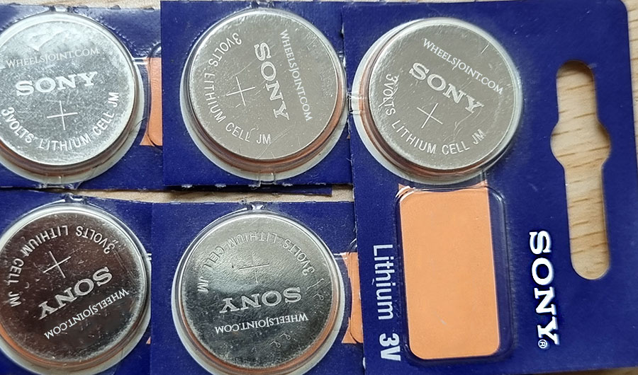
Replace the battery
If the button cell battery in the key fob of Voyager is replaced incorrectly or a battery is unsuitable, it can damage the vehicle key. Only replace drained batteries with new batteries in the same voltage, size, and specification. Make sure the battery is facing in the right direction when inserting it.
Recommended video
Key fob not working after replacing the battery
When purchasing a new battery for the key fob of your Voyager, keep in mind that the battery may be sitting on the shelf for a long time. Therefore after replacement it may not work, or may not last that long. Try purchasing the battery from a store where stock moves fast. If you still can’t get the key fob to work after verifying that the battery is healthy, your key fob issues may not be due to bad battery.
Starting the engine with dead key fob battery
If your Voyager has push button start/stop feature, your vehicle may not start due to weak key fob battery and a ‘key not detected’ alert message may be displayed in the instrument cluster. Don’t worry, you can still start your vehicle, the immobilizer is controlled by a passive transponder. Passive means, among other things, that the transponder in the key does not need its own power source.

Touch the start/stop button with your key fob and then start the engine. If it doesn’t work, then look in the owners manual for exact location of key fob placement, as it may vary depending on model.
Use spare key: You can try starting your Voyager with its second key. It will also rule out any other problem with the first key, for example, water damage.
How long does the key fob battery last?
Depending on how often you use the key fob or remote control of your Voyager, the battery should last between two and four years. This is assuming the new battery you installed is healthy and its use by date is many years away.
2. Poor battery connection
The battery inside the key fob of Voyager has metal retaining clips that hold the battery in position and completes the circuit. If the clips don’t have any tension, it can cause contact issues and the remote may not receive any power. Make sure the battery is firmly placed and does not move around when you shake the remote. Also make sure all the battery contacts are corrosion and dust free.
3. Water damage
If your Chrysler Voyager key fob has taken a bath in the soapy water of the washing machine after you forgot to take it out of your pants pocket, water damage is very likely.
Water resistant, not waterproof
Your Voyager key has rubber seals which prevents the water from getting to the electronic chip inside. A splash of water or brief exposure to light rain should be fine, but exposure to excessive amount of water like submerging the key in the pool can cause the water to penetrate the seals and damage the chip. Submerging the key in ocean water at the beach can be much more damaging to key fob electronics due to highly conductive nature of salt water.
But my key fob survived water exposure?
If your Voyager key fob survived a wash cycle, or a deep bath in the ocean or pool water, it doesn’t make the key fob waterproof, it means you got lucky. Exposure to excessive water increases the risk of water damage, so you shouldn’t make this a habit.
What to do in case of water damage?
If your Voyager key fob stopping working after exposure to clean tap water or rain, immediately remove the battery and clean the electronic component with paper towel and let it dry fully before putting back the battery. In case of exposure to salt water, or soapy or dirty water, it is recommended to clean the chip with isopropyl alcohol or electronic cleaner. If the key fob still doesn’t work after cleaning and drying, the chip is probably fried and you will have to buy a new key.
4. Dead 12 volt battery
The remote keyless system and the central locking system in Voyager require the 12 volt battery to be in healthy state to function properly. If the 12 volt battery is dead or if the electric current has been interrupted due to corrosion on the battery terminals or the ground connection, all on-board electronics will stop working.
In this case, you will have to manually unlock the door of your Voyager with physical key. Also, the electrical accessories (e.g. headlights, fan, and infotainment system) will not function or may function poorly, and the engine will not start. Check the 12v battery and its connections.
5. Signal interference
Voyager remote control signal can be disrupted by objects, poor weather conditions or transmitters on the same frequency band close to the vehicle. The remote key may work when you’re near the vehicle, but may not work from a distance. In case of severe interference, the remote may not work at all.

Interference signals can be caused not only by neighboring radio masts and towers, but also by unprofessionally installed satellite systems. A large part of the radio interference is caused by defects and aging effects in electrical devices and radio systems, which lead to unwanted emissions, radiation and repercussions on power and communication networks. Your Voyager key fob should start working again when you leave the area of interference.
6. Reprogramming required
In rare cases, the remote key of Voyager may stop working due to pairing issues. The key can be reprogrammed with an OBDII scanner. You may also be able to program a key by following a few steps, an original key is typically required for successful pairing. The instructions should be mentioned in the owners manual. If you fail to do it yourself, you may have to visit an authorized dealer for reprogramming of the key.
7. Defective key fob
If your Voyager key fob stopped working after you dropped it on the floor, you may have damaged the internal chip. Or, if your key fob just stopped working one day out of the blue, in rare cases this could indicate a faulty key fob – assuming you have tried everything to fix the issue e.g. battery replacement, reprogramming and the spare key fob works.
8. Faulty receiver module
Chrysler Voyager has a remote keyless system receiver that receives radio frequency signals from the key fob. If none of your key fobs work, and and you can’t reprogram the keys, it is possible the receiver module has developed a fault.
You may have to perform further diagnostics to identify the faulty. The keyless entry antenna could be damaged, or the module is just not communicating with other modules on the vehicle. In these cases an OBDII scan tool can be used to verify if the commands are being transmitted and acted on by the security module.
9. Electronic immobilizer fault
The immobilizer is an anti-theft security system that prevents the engine from being started and the vehicle from being moved with an unauthorized vehicle key. A fault in the immobilizer system can prevent your Voyager from being started. You may also see a warning light with key symbol or key not detected message in the instrument cluster.
For vehicles with an ignition lock
There is a chip in the vehicle key. The chip automatically deactivates the immobilizer if a valid vehicle key is inserted into the ignition lock. The electronic immobilizer is activated automatically when the vehicle key is removed from the ignition lock.
For vehicles with a starter button
There is a chip in the vehicle key. It is used to automatically deactivate the electronic immobilizer when there is a valid remote control vehicle key in the vehicle interior. The electronic immobilizer is automatically activated as soon as there is no valid vehicle key in the vehicle.
The engine can only be started with a genuine vehicle key that is coded correctly. You can obtain coded vehicle keys from an authorized Chrysler dealer.
Reset the system
If the key fob is not working due to a glitch in the keyless entry system, it may be possible to restore the functionality by resetting the keyless entry system in your Voyager.
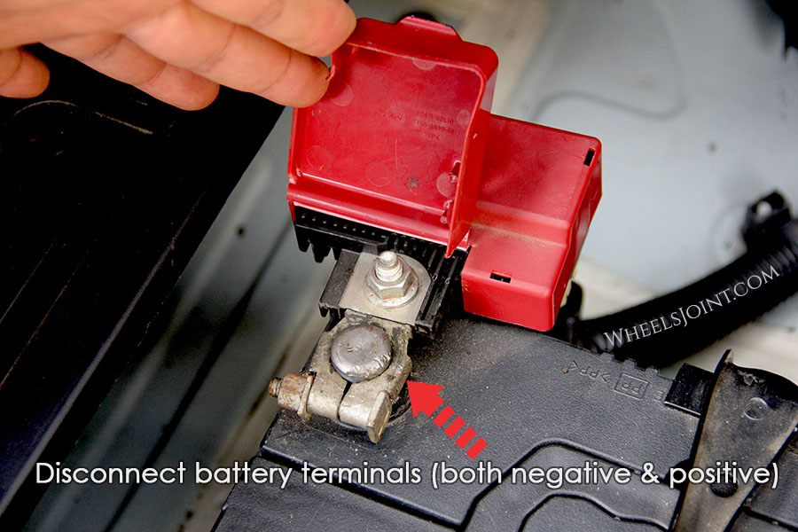
There isn’t any button or option to reset the keyless entry system in Voyager, but you can reboot all the on-board computers by disconnecting the 12 volt battery for a few minutes. Remove the cable from the negative terminal of the battery first, then from the positive terminal. With the battery disconnected, press the horn button a few times and turn on the headlights to drain out all the residual electricity from the system. After about 15 minutes, reconnect the battery in reverse order: positive cable first, then negative cable.
Use OBD2 scanner for diagnosis
Since Chrysler Voyager is equipped with on-board diagnostics (OBD), a fault diagnosis can provide initial indications of where the malfunction is located. This method will be especially useful when diagnosing a faulty remote keyless system receiver module.
To begin troubleshooting, you must first connect the diagnostic tool to your Voyager. The OBDII connector is usually located under the dashboard. With the tool connected, turn on the ignition. Most diagnostic devices then ask for some information about the vehicle. It is important that you enter this 100% correctly, otherwise the result of the search may be inaccurate. In addition to the vehicle make, model, and engine type, you usually also have to type in the Vehicle Identification Number (VIN). Since some OBD codes are manufacturer-specific, the scanner will be able to give you more accurate information if you enter more details about your Voyager.
Conclusion:
There are many reasons why your Chrysler Voyager key fob is not working. When looking for the reason, you should start with the most obvious cause that is easy to diagnose: dead battery, which you can replace in a few minutes.

- Kia Optima makes grinding noise when starting – common causes
- Ram ProMaster bad O2 sensor symptoms, causes, and diagnosis
- Mazda6 bad spark plugs symptoms, causes, and diagnosis
- Peugeot 308 pulls to the right when driving
- Toyota Corolla AC not blowing hard enough – weak airflow causes
- Audi TT RS bad wheel speed sensor symptoms – how to diagnose
- Kia Seltos dirty cabin air filter symptoms, when to replace
- Lincoln Navigator uneven tire wear causes
- Aston Martin DBX pulls to the right when driving
- Porsche Cayenne AC not cooling – causes and diagnosis
- Lexus GX bad alternator symptoms, how to check voltage
- Chevy Silverado 2500 HD bad spark plugs symptoms, causes, and diagnosis
- Nissan Armada makes sloshing water sound – causes and how to fix it
- Toyota Hilux dead battery symptoms, causes, and how to jump start
- Fiat Tipo makes sloshing water sound – causes and how to fix it
- VW Touareg Bluetooth not working – causes and how to fix it
- Is Buick Park Avenue key fob waterproof?
- Chevy Tahoe bad wheel speed sensor symptoms – how to diagnose
- Vauxhall Astra dirty cabin air filter symptoms, when to replace
- Chrysler Grand Voyager bad O2 sensor symptoms, causes, and diagnosis
IMAGES
VIDEO
COMMENTS
Genuine Chrysler Grand Voyager 5 Button Fobik Remote Chrysler Part Numbers: 56046710AE / 56046710AF / 56046710AG 5 Buttons: Lock, Unlock, Boot, Left Door and Right Door Transponder: ID46 - PCF7941 Frequency: 433 Mhz Battery Type: CR2032 Key Blade: Y160 ISN: Genuine Chrysler remote key supplied with the original manufacturer packaging.
Chrysler 2002 Chrysler Grand Voyager Remote FCC ID: GQ43VT13T, GQ43VT17T. $29.95. Add to cart. Quick view. Chrysler 2002 Chrysler Grand Voyager GQ43VT18T Remote. From $49.95 $94.35. Choose options. Quick view. Chrysler 2001 Chrysler Grand Voyager Remote FCC ID: GQ43VT13T, GQ43VT17T.
Chrysler Grand Voyager Key Programming in both lost case and Adding New Key using XPad 2. Pincode reading is supported by device so no need to take that fro...
Replace the battery. If the button cell battery in the key fob of Grand Voyager is replaced incorrectly or a battery is unsuitable, it can damage the vehicle key. Only replace drained batteries with new batteries in the same voltage, size, and specification. Make sure the battery is facing in the right direction when inserting it.
This video will show you How To Replace Plymouth Grand Voyager Chrysler Grand Voyager Key Fob Battery 2001 2002 2003 2004 To Order This Remote Visit: https:/...
Shop wholesale-priced OEM Chrysler Grand Voyager Car Keys at MoparPartsGiant.com. All fit 2000 Chrysler Grand Voyager and more. ... Chrysler Grand Voyager Key-Blank. Part Number: 4778115. Vehicle Specific. Other Name: Key Blank 84 Groove; Key $17.21 MSRP: $ 24.90. You Save: $7.69 (31%)Check the fit. Add to Cart. More Info.
Order Chrysler Grand Voyager Vehicle Key online today. Free Same Day Store Pickup. Check out free battery charging and engine diagnostic testing while you are in store.
Description. This service is for Chrysler 5 button remote key fob faulty on central locking operation, starting or having a damaged or worn housing. Here at Car Keys Solutions we test the remote key to start with and then repair/ refurbish your remote using new housing and internal parts as required to make your car key remote like new.
Genuine Chrysler Grand Voyager Remote Key. Part Number: 68060264AA. Suitable for: Chrysler Grand Voyager (2005 - 2009) Product Availability. You can see the stock status of the part under the 'add to basket' button. Parts marked as 'Availability: In Stock' are available in our warehouse for same day shipping.
Shop wholesale-priced OEM Chrysler Voyager Car Keys at MoparPartsGiant.com. All fit 2000-2020 Chrysler Voyager and more. ... Chrysler Voyager Key Fob-Integrated Key Fob. Part Number: 68419652AB. Vehicle Specific. Other Name: Transmitter; Replaced by: 68419652AC $127.46 MSRP: $ 189.00. You Save: $61.54 (33%)Check the fit. Add to Cart.
The most common cause of key fob not locking or unlocking the doors in Chrysler Grand Voyager is dead coin battery inside the key fob. But the remote control can also stop working due to worn buttons, poor battery contact, water damage, receiver module issues, signal interference, dead 12 volt battery, unpaired key requiring reprogramming, or ...
Page 453 BULGARIA CHILE CHINA BALKAN STAR Comercial Chrysler S.A. Chrysler Group (China) Sales Limited Resbarska Str. 5 Av. Americo Vespucio 1601, Quilicura No. 1509, Building# 63, Dongsanhuan Middle Road 1510 Sofia Santiago, Chile Beijing Tel.: 359 2 91988 Zip Code 101931-7, 367-V PR.
A high-quality aftermarket replacement key. Compatible with the following models: Chrysler Voyager with Electric sliding doors 2004-2010 Grand Voyager with Electric sliding doors 2004-2010 Comes complete with; Blank uncut CY24 blade 5+1 buttons New remote control key fob Battery Frequency 433 MHZ PCF7941A / HIT
Grand Voyager. Page 1 of 1. Chrysler Grand Voyager key Y160-PT £6.00. Chrysler Grand Voyager replacement key used from 1999 to 2009.
Insert the blank key into the ignition and turn it to the RUN position. Using a DRBIII (R) scan tool, select "Theft Alarm, " "SKREEM, " "Miscellaneous, " and then "Program New Key." Enter the four digit PIN code using the DRBIII (R) scan tool. When programming is completed, the SKREEM will exit Secured Access Mode and the DRBIII (R) scan tool ...
1. Using a functional key fob transmitter, unlock the vehicle and disarm the Vehicle Theft Security System. 2. Insert ignition key into the ignition switch. 3. Turn the ignition switch to RUN position with- out starting engine. 4. Using a functional key fob transmitter, press and hold the UNLOCK button for a minimum 4 seconds (maximum 10 seconds).
Chrysler Grand Voyager (2005 - 2009) quantity + Add to basket. Free Key Courier Collection & Return Delivery. ... Once the repair has been carried out the remote key is tested again to confirm the functionality has been restored. Make Model Year ; Chrysler : Grand Voyager : 2005 - 2009 :
Using a previously programmed transmitter, press the UNLOCK button for 5 to 10 seconds. While the UNLOCK button is being pressed, press the PANIC button and release both buttons simultaneously. You will hear a chime sound to signal you that programming on the new transmitter (s) may occur. 3.
White Knight Wheel Lock Key Locking Lug Nuts 241705. Notes: 12 mm x 1.50 thread size, 3/4" and 13/16" hex. Specialty. Refer to your owner's manual or wheel manufacturer's guide for correct thread size, seat style, length, hex and torque specifications. Improper installation can result in accident and/or injury. 4 package, open end bulge lock.
Facts at a Glance. Chrysler Grand Voyager 2.8 CRD Limited Price range: 1.8 million — 2.2 million rubles ($54,300 — $66,400) Technical Specifications:
Replace the battery. If the button cell battery in the key fob of Voyager is replaced incorrectly or a battery is unsuitable, it can damage the vehicle key. Only replace drained batteries with new batteries in the same voltage, size, and specification. Make sure the battery is facing in the right direction when inserting it.
Chrysler Model: Town & Country Body type: Minivan Doors: 4 doors Drivetrain: Front-Wheel Drive Engine: 283 hp 3.6L V6 Flex Fuel Vehicle Exterior color: ... Chrysler Voyager. Chrysler PT Cruiser. Chrysler Sebring. Chrysler Crossfire. Chrysler Aspen. Chrysler Prowler. Chrysler 300M. Company; About CarGurus. Our Team. Press. Investor Relations.
New and used Chrysler Grand Voyager for sale in Moscow, Idaho on Facebook Marketplace. Find great deals and sell your items for free.