
Galvin Power is reader-supported. When you buy via our links, we may earn a commission at no cost to you. Learn more

What is a Shunt Trip Breaker and How Does It Work?
Written by Edwin Jones / Fact checked by Andrew Wright

What is a shunt trip breaker? Does it add protection to your electrical system?
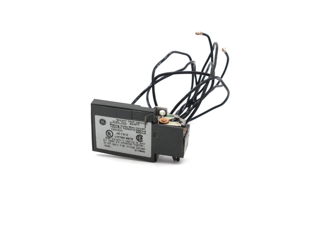
The shunt trip breaker is a combination of the shunt trip accessory and the main circuit breaker. This installs on the main breaker to add protection to your electrical system. This adds security to your electrical system as it manually or automatically cuts the electric supply in your circuit.
This accessory can help prevent short circuits and avoid electrical damage should a disaster occur in your home.
Let me tell you more about the shunt trip breaker to help you decide if you need additional protection for your electrical system.
Table of Contents
What is Shunt Trip Breaker and How Does It Work
Where are shunt trip breakers most used, how to install a shunt trip accessory to the breaker.

You should know that shunt trip breakers are different from GFCI circuit breakers.
The GFCI circuit breaker contains one big white tail wire for neutral connections only. It cannot be connected to any control package because the GFCI circuit breaker is solely designed to detect a sudden electrical surge. It has no other purpose but to cut power in case of a short.
Meanwhile, the shunt trip breaker wiring comprises two wires. One connected to the ground, and another to a control system. The control system can be connected to a sensor or to a manual switch. When activated, the shunt trip accessory will cause the main breaker to trip.
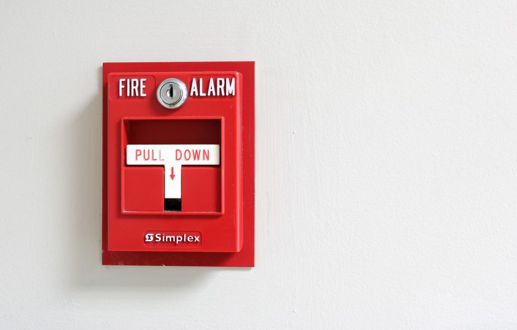
For example, if you install a shunt trip with a smoke detector, it will activate and cut off the power should the smoke sensor trigger. It can also be installed with a remote switch , allowing you to trip your breaker manually.
It is crucial to know the difference between a regular circuit breaker and a circuit breaker installed with shunt trip accessories.

The shunt trip definition means that it is a way to cut off electrical power through other sensors, not just via thermal activation. Since this is an optional accessory for a circuit breaker, it is not required for a home electrical system.
However, it is recommended for added safety. This is especially true if you’re working with industrial machinery. Furthermore, you can use it as a manual emergency switch to shut down your main breaker.
Before installing a shunt trip, consider its cost and your existing system. You may need to change the breaker panel and circuit breakers, especially if it is not compatible with shunt trips. You may also need a new line to connect the remote emergency switch to your breaker box.
Generally, most commercial kitchens, elevators, and offices have this shunt trip breaker because it is required. Commercial kitchens use this device in compliance with ANSI/ASME CSD-1, while elevators and escalators comply with ASME A17.1. These codes refer to the controls and safety standards provided by ASME’s.
This question is a topic of discussion among Reddit members as well. Join the conversation here:
Found at a dominos by u/Guilty_Sympathy_496 in electricians
Mostly, installing a shunt trip relay requires that the breaker and the shunt be from the same maker. Also, not all breaker models are compatible with this accessory.
Once you’re sure that your system can take a shunt trip accessory, installation is pretty much straightforward. You can watch this video by Aaron CBIONE for some tutorials.
Note: Every circuit breaker comes with different instructions. It would depend on the brand and model of the breaker .
However, the critical part of every installation is that you need to connect the shunt to your sensor. You may need a shunt trip breaker diagram as a reference to ensure correct installation.
Also, check the brand and model of your breaker before proceeding with the installation. Some makers only allow a factory install of the shunt trip and other accessories. DIY installation may void the warranty of your breakers. It’s best to read up on the manual or consult an electrical professional before making any changes.
What is a shunt trip breaker? The shunt trip is an optional accessory for a circuit breaker for added protection to your system. It is designed to connect to a secondary sensor. It will trip the breaker automatically if the sensor is triggered. It can also be activated via a remote switch that you can install.
Do you think that a circuit breaker is enough to protect your investment? Or do you want an additional layer of protection for your electrical circuit? If you’re not decided yet, reach out to me in the comments section below, and I will be happy to help you.

I am Andrew Wright. With 8 years of experience designing, installing, and maintaining electrical power systems. I love my job, and I have always wanted to offer others the necessary help so they can take care of their houses.
- Electrical Repair
- Lighting Installation
- Hot Tub Wiring
- Emergency Electrical Service
- Ceiling Fan Installation
- Generator Installation
- Commercial Lighting Services
- Electrical Inspection
- What Is a Shunt Trip Breaker and How Does It Work
What Is a Shunt Trip Breaker and How Does It Work?
First things first: what is a shunt trip breaker? A shunt trip breaker is a specialized circuit breaker that is designed to remotely shut off power to a circuit in emergency situations, such as a fire or security breach. These breakers are commonly used in commercial and industrial buildings, as well as other facilities where safety is a top priority. In this article, we'll explore this type of breaker in detail and explain why hiring an electrical services provider for a wiring shunt trip breaker is essential.
The Many Benefits of a Shunt Breaker
Let’s recap: a shunt trip breaker is an electrical component connected to a circuit breaker and allows for remote operation through a schematic and AMP connection. Now that you know what a shunt trip circuit breaker is, it's time to move to the next part of this article: the benefits of using a shunt breaker.
- Remote Shut-Off: One of the main benefits of shunt breakers is that they can be remotely shut off in the event of an emergency. This allows them to quickly and easily disconnect power in a fire or other emergency, which can help prevent damage to the building and protect the occupants.
- Increased Safety: Besides remote shut-off, shunt trip circuit breakers provide an added level of safety and security by automatically shutting off power to a circuit in the event of an emergency. This helps prevent electrical fires and other hazards, protecting both people and property.
- Easy Installation: Shunt breakers are relatively easy to install and can be integrated into existing electrical systems, making it possible to retrofit older buildings with these devices.
- Cost-Effective: A shunt breaker is a cost-effective solution for increasing safety and security in commercial and industrial buildings. They are relatively inexpensive to purchase and install and can help prevent costly damage to the building and its contents in case of any emergency.
- Compatibility: Shunt breakers are compatible with a wide range of electrical systems and devices, making them a versatile and practical solution for increasing safety in various settings.
How Does a Shunt Trip Breaker Work?
A shunt trip breaker works by tripping the breaker when it receives a signal from an external device, such as a fire alarm or security system. This helps to prevent dangerous electrical fires or other hazards. When an emergency occurs, the external device sends a signal to the breaker, which causes the breaker to trip and open the circuit, interrupting the flow of electricity and preventing power from reaching the circuit, allowing for a quick and easy power disconnection.
Types of Shunt Trip Breakers
Now that you know the answer to "How does a shunt trip breaker work", it's time to discover about the two main types of shunt trip breakers.
- Manual Shunt Trip Breaker: This type of trip breaker requires manual intervention to reset the breaker after it has been tripped, meaning someone must physically go to the breaker and reset it after an emergency situation. This breaker is typically used in smaller residential buildings or situations where a dedicated staff member is available to reset the breaker.
- Automatic Shunt Trip Breaker: This type of breaker can automatically reset itself after being tripped and is typically used in larger buildings or in situations where there is not always someone available to reset the breaker. These breakers are often connected to fire alarm systems or other emergency management systems for auto-reset.
When is a Shunt Trip Breaker Required?
If you're wondering when is a shunt trip breaker required, know that it is required in any electrical system where there is a need to quickly and easily shut off power in the event of an emergency, such as a fire or security breach. Continue reading as we describe the importance of using shunt trip breakers and how to figure out which one you need to use for your building or facility.
The Importance of Using a Shunt Trip Breaker
- Shunt trip breakers automatically shut off power in emergencies.
- They prevent dangerous electrical fires and other hazards.
- They allow for quick and easy power disconnection in emergencies.
- They are easy to install and cost-effective solutions for increasing safety.
- They can be connected to fire alarm and emergency management systems.
- They ensure that the electrical system is in compliance with safety regulations.
- They are a versatile and practical solution for increasing safety in various settings.
Which Type of Shunt Trip Breaker to Use?
A manual breaker may be appropriate for a smaller building or in situations with a dedicated staff member available to reset the breaker, while an automatic breaker may be more appropriate for a larger building or in situations where someone is not always available to reset the breaker. Another option to consider is the use of a shunt trip relay, which can be used to trigger a shunt trip breaker remotely. These relays are typically connected to fire alarm systems or other emergency management systems and can send a signal to the breaker to trip it when an emergency occurs.
Shunt Trip Breaker Wiring Diagram

If you're wondering how to wire a shunt trip breaker, know that wiring can seem like a daunting task, but with the right knowledge and tools, it can be done relatively easily. Follow the steps below:
- Obtain a "How to wire a shunt trip breaker wiring diagram." (Check above).
- Gather necessary tools and materials such as wire strippers, nuts, and a voltage tester.
- Disconnect the power and wire the shunt breaker according to the instructions provided.
- Reconnect power to the circuit and test the breaker to ensure it works properly.
It is important to pay close attention to the diagram and follow the instructions carefully. This will ensure that the breaker is wired correctly and functions. Once the wiring is complete, you can reconnect the power to the circuit and test the breaker to ensure that it is working properly. It is always better to consult with a professional if you aren't confident about the wiring process.
What Does a Shunt Trip Breaker Do?
We hope by now you know what does a shunt trip breaker do, but here's a recap: a shunt trip breaker is a specialized circuit breaker that protects your house electrical systems from damage or hazards in emergencies. It works by tripping the breaker when it receives a signal from an external device, such as a fire alarm or security system, preventing dangerous electrical fires or other regular hazards.
Nevertheless, it is important to understand what does shunt mean in electrical terms and the role of electrical shunt trip breakers in commercial and industrial settings. Finally, to determine the appropriate type of breaker for your specific needs, it is best to consult an electrical services provider. If you're based in Colorado or surrounding areas, McCarrick Electric has got you covered.
Superior Electrical Solutions in Colorado
At McCarrick Electric, we have 25+ years of experience providing top-quality electrical services in Colorado. We value all of our customers, and that's why we offer a 15% discount for first-time residential clients and veterans. We take pride in our integrity, attention to detail, and cost-effectiveness. For more information, connect with us via our contact form or give us a call.
Latest Blog Entries

What to Do If Your Circuit Breaker Keeps Tripping?

Why Is Your Breaker Box Outside House? Here Are the Reasons

Why Won’t My GFCI Outlet Reset? How to Troubleshoot a GFCI Outlet

5 Ways to Prevent Short Circuits
What Is A Shunt Trip Breaker & How Does It Works?

Have you ever heard about this kind of breaker? And “what a shunt trip breaker is” usually appears when you hear about this for the first time.
Keep this article to get the best answer to the question above, its primary use, and when it is required.
Table of Contents
What Is A Shunt Trip Circuit Breaker?
A circuit breaker “trips” once it detects a problem, cutting off power to the outlet or appliance in question and protecting the wire from burning.
An optional attachment to any circuit breaker, a shunt trip breaker allows for the breaker to be shut off remotely at any moment or immediately in the event of a power excess. Damage to or injury from equipment may be avoided in a crisis if this is in place.
There are two distinct categories for shunt trip breakers, automatic and manual. The breaker may be turned off from the exterior of the building through a remote button using manual switches. Conversely, mechanical switches interrupt power flow when they identify a surge coming from the grid.
How Does A Shunt Trip Breaker Work?

Electrical impulses often pass through your circuit breaker without being altered. Nevertheless, if these currents reach unsafe levels, an additional surge of energy will charge a magnet located just below the primary breaker switch. This will cause the switch to trip, resulting in the power being cut off.
Adding a shunt trip breaker provides an additional method to charge the magnets and trip the switches, which makes it possible to turn off the electricity remotely or automatically.
Some of the shunt trips are powered by an external source. When a power surge occurs at this source, a notification is delivered from the shunt trip towards the breaker, which causes the breaker to stop the power automatically.
Connecting to a remote switch that is situated outside the building may also be accomplished with the help of a shunt trip. The current is cut off when the user clicks a button on that switch, which causes an electrical surge to be sent via the shunt trip circuit.
Even though shunt trip breakers are optional in residences, many people put them there out of caution. But, these devices are also often used in businesses that use expensive industrial machinery or electronic wiring that are susceptible to being destroyed in the event of a power surge.
Why Are Shunt Trip Breakers Important?
In an unexpected power outage, you may give yourself an additional level of peace of mind by installing a shunt trip breaker in your house. Because of this, you will not risk injuring yourself or creating any electrical harm.
If there is a fire, one of the most common uses for shunt trips is to switch off any electrical equipment that could be present. For example, when a shunt trip is connected to a fire detection system, the power may be immediately turned off once the smoke detector senses a fire. This allows for eliminating any potential electrical hazards that the fire may cause.
If your smoke detector is connected to your home’s sprinkler system, installing a shunt trip is essential. This device might turn off your power as quickly as the smoke detector triggers the sprinkler, reducing the real damage to your electronic devices.
Where Do People Most Often Use Shunt Trip Breakers?
Shunt trips reduce power through additional sensors, not simply heat activation. For a household electrical system, this circuit breaker attachment is optional.
However, it’s advised for safety. Industrial equipment makes this particularly true. It may also shut off your main breaker manually in an emergency.
Before beginning the implementation of a shunt trip, take into consideration the associated costs and the system. It is possible that the breaker panel and the circuit breakers will need to be replaced if shunt trips are not supported. It’s also possible that a new cable will be required to connect the remote emergency switch to the breaker box.
In most business kitchens, elevators, and offices, shunt trip breakers are an essential safety device. ASME A17.1 is the standard that must be adhered to for elevators and escalators, while ANSI/ASME CSD-1 is the standard that must be attached to commercial kitchens. ASME regulations mandate these controls and safety standards.
Installing A Shunt Trip Accessory to a Breaker
Shunt trip relays can only be installed with breakers and shunts made by the same company. Plus, not all circuit-breaker models can use this part.
Adding a shunt trip connection is easy after establishing that your system is functioning. Watch this video from Schneider Electric for some guidelines:
Each circuit breaker has its instructions, so please follow them carefully. In addition, the make and model of the breaker are relevant.
The most critical step when setting up a sensor is to attach the shunt. If you want to be sure your shunt trip breaker is installed correctly, a shunt trip breaker diagram may be required.
It’s essential to verify the model and manufacturer of your breaker before commencing the installation. The manufacturer in some instances can only install the shunt trip and any other components. If you install your circuit breakers on your own, you might void the warranty. If you want to make alterations, you need either consult the manual or an electrician.
Here are some questions and answers related to the shunt trip breaker:
Does Shunt Trip Breaker Work?
Shunt trip breakers serve a vital purpose in the electrical system as a whole by providing an extra layer of protection for the circuits they are part of. In addition, they cut off electricity in times of crisis to avoid harm and damage to equipment.
What Are 3 Types Of Shunt Trip Breakers?
- Standard breakers
- Around fault circuit interrupter circuit breakers (GFCIs)
- Arc fault circuit interrupter circuit breakers
They are the three fundamental circuit breaker types (AFCIs). And standard breakers include both single-pole and double-pole circuit breakers.
Why Is Shunt Used In MCCB?
Molded case circuit breakers (MCCBs) are often employed in electrical distribution systems to prevent overload and short circuits from damaging electrical components. In reaction to a voltage signal from the outside, the shunt release device, a built-in component of MCCB, releases the mechanism.
You have completely got the answer to what a shunt trip breaker is and understand its function.
A circuit breaker’s shunt trip is an extra layer of safety that may be installed if desired. It’s meant to link up with another sensor. If the sensor is activated, the breaker will trip immediately. You may also set up a remote switch to turn it on and off.
- Why does my breaker keep tripping with nothing plugged in?
- Crouse hinds compatible breakers
- Challenger breaker replacement

Erik Watkins
Automotive Mechanic at PowerAll
With 7 years experience in management positions leading automotive mechanics at PowerAll, Erik Watkins wishes to share useful knowledge and information about automotive mechanical equipment.
Submit a Comment Cancel reply
Your email address will not be published. Required fields are marked *
Save my name, email, and website in this browser for the next time I comment.
Submit Comment

What Is A GFCI Outlet Receptacle? What Does It Stand For?

Gas vs. Electric Lawn Mower: Is Battery As Good As Gas?

Extension Cord Gauge/Length Chart: Amp Rating & Size

Dimmable LED Flash: LED Light Bulbs Flickering Solutions

Crouse Hinds Compatible Breakers & Replacement Chart

What Size Wire For 40 Amp Circuit Breaker?
Electrically Safe Work Practices — NFPA 70E Basics

Workforce Development and its Role in Electrical Safety

EFCOG Best Practice #240 — Electrical Utility Risk Assessment

Guide to Ground Fault Sensing
Ground faults arise when current flows from an energized conductor to ground inadvertently. The return path of the fault current is through living beings or equipment touching the grounding system. Ground fault detection is critical to protecting people and animals from shock or death.
It doesn’t take much ground-fault current to cause harm. Extensive research in the 1960s determined the amount of current and voltage needed to cause ventricular fibrillation (where a heart stops beating) in humans. These studies found that as little as 70 mA through the heart was enough to cause fibrillation. The refinement of transistor technology provided a means of sensing currents as low as 0.003 A (3 mA) to energize a relay that would decouple the power supply.
OSHA documents spell out the general relationship between the amount of current received and the reaction when current flows from the hand to the foot for just one second.
- At 1 mA, you feel a slight tingle.
- At 5 mA, you feel a slight shock, not painful but disturbing. The average individual can let go, but involuntary reactions can lead to injuries.
- At 6–25 mA, there is painful shock, and muscular control is lost.
- The 9–30 mA level is called the freezing current or “let-go” range. At this level, many humans cannot get their muscles to work, and they can’t open their hand to let go of a live conductor.
- At 50–150 mA, there will be extreme pain, respiratory arrest, and severe muscular contractions. The individual cannot let go, and death is possible.
- At 1,000–4,300 mA, there is ventricular fibrillation. Muscular contraction and nerve damage occur. Death is most likely.
- At 10,000+ mA, there will be cardiac arrest with severe burns and probable death.
Besides endangering lives, ground faults can also lead to costly fires and other equipment damage. Numerous safety regulations and electrical codes exist to prevent and protect against ground faults.
Ground fault regulations
The size of conductors, set points, and subsequent actions are all considerations for selecting a ground fault sensor. What do the local codes require for protection and disconnect? What is the main goal in setting up a ground fault device? Is it focused on personnel protection or electrical device/process protection?
In North America, ground fault circuit interrupters (GFCI) have been required by the National Electric Code (NEC) since the late 1960s. As the technology became more reliable, the NEC mandated GFCIs in many more applications to reduce the number of deaths from electrical shock.
GFCI receptacles and circuit breakers were a huge step forward from prior designs using core balance transformers connected to current sensitive relays. The compact form factor, one-piece design, and simple installation of receptacles and circuit breakers resulted in a significant reduction in fatalities leading to a greater interest in ground fault protection. The NEC sets requirements for where a GFCI will be installed. The system design engineer follows the NEC requirements based on Underwriters Laboratories standard UL 943, Ground-Fault Circuit-Interrupters . The UL specification designates what fault current level will cause the circuit to be de-energized, how quickly it must disconnect, and several other points, including a self-test function. The minimum amount of latency between when the fault occurs and when the circuit is de-energized is based on a mathematical formula so that more time can elapse when the fault is low than when the fault is more severe:
The Time in seconds (T) = (20 / F I) [ fault current in mA to the power of 1.43].
T = (20 / 6) 1.43 = 5.593 for a fault of 6 mA.
The circuit must be disconnected in 5.59 seconds to meet this requirement. If the fault is more significant at 30 mA, the circuit must be de-energized in 0.56 seconds, 560 ms. If the fault is 250 ms or higher, the monitored circuit must be disconnected in 25 ms.
The NEC refers to personnel protection as ground fault circuit interrupters tested to UL 943A requirements, while in Canada, the standard is CSA (Canadian Standards Association) C22.2 and in Mexico NMX-J-520 from UL.
Industrial ground fault sensors should be marked as recognized under UL 1053 (Standard for Ground-Fault Sensing and Relaying Equipment) , UL 508 (Standard for Industrial Control Equipment) , or one of the other categories of UL 943: Class B, C, or D.
- UL 1053 is specific for ground fault sensing and relaying equipment with no stated current levels or time to operate.
- UL 508 is an even broader category that covers a variety of automation components.
When using a ground fault sensor to control a shunt-trip breaker, both components (sensing device and circuit breaker) must be tested together to verify the circuit is interrupted quickly enough to be considered a GFCI that meets UL 943 requirements, and that the two parts, sensing and disconnecting method, meet the other specific UL requirements for this standard.
Protecting processes
While personnel safety is a major concern of ground fault protection, industrial settings dictate additional considerations. Manufacturing facilities normally employ a variety of safety protections for employees working with electrical machinery. Personal Safety Devices (PSD) used properly help minimize exposure to electrical dangers and allow fault current trip levels to be safely raised, minimizing nuisance trips and preventing undesired process interruptions. Ground fault detection can also be used to initiate controlled stops, alert other upstream processes, and even be used as part of a predictive maintenance program to repair or renovate equipment before a complete breakdown can occur.
The requirements of UL 943 for personnel protection (avoiding shock to humans) are well established and under constant refinement, while standards for equipment protection are less stringent. The primary aim of equipment protection is to keep a fault from damaging machinery. Circuits supplying heating loads (heat strips, heat trace, and snow melting equipment) are usually not disconnected until the fault current exceeds 30 mA or more. Electric vehicle charging stations are now required to have GFCI personnel protection according to 625.22, under a separate UL Standard, UL 2231-1 (Standard for Safety for Personnel Protection Systems for Electric Vehicle (EV) Supply Circuits: General Requirements).
The 2017 NEC says the following:
Ground-fault protection of equipment shall be provided for fixed outdoor electric deicing and snow-melting equipment. [Section 426.28]
Section 427.22 also requires that:
Ground-fault protection of equipment shall be provided for electric heat tracing and heating panels. This requirement shall not apply in industrial establishments where there is alarm indication of ground faults, and the following conditions apply:
1) Conditions of maintenance and supervision ensure that only qualified persons service the installed systems, and
2) continued circuit operation is necessary for the safe operation of equipment or processes. [Section 427.22]
The 2020 NEC states:
Ground-fault protection of Equipment: Ground-Fault protection of equipment shall be provided for fixed outdoor electric deicing and snow-melting equipment. [Section 426.28]
2017 NEC states:
The overcurrent protective devices that supply the marina, boatyards, and commercial and noncommercial docking facilities shall have ground-fault protection not exceeding 30 mA. [Section 555.3]
For the 2020 NEC , the ground-fault protection (GFP) requirements of marinas, boatyards, and docking facilities was extensively revised. These GFP requirements (previously located at 555.3) were divided into three parts to provide clarify for these important ground-fault requirements. Section 555.35(A)(1) addresses shore power receptacles with individual GFPE not to exceed 30 milliamperes (mA). Section 555.35(A)(2) addresses 15- and 20-ampere receptacles for other than shore power with Class A GFCI protection (4 to 6 mA) being provided in accordance with 210.8 through a reference at 555.33(B)(1). Section 555.35(A)(3) addresses feeder and branch-circuit conductors providing power to individual slips or piers and installed on docking facilities to be provided with GFPE set to open at currents not exceeding 100 mA with coordination with downstream GFPE permitted at the feeder overcurrent protective device.
The 2017 NEC calls for ground-fault protection for high-current supplies, too. Sections 215.10 and 230.95 deal with currents of 1,000 A or more and voltages of 480 or higher. Section 517.17 also stipulates where fault detection is required in hospitals and other health care facilities.
The importance of protecting an electrical system against faults-to-earth cannot be overstated. This type of fault sensing is not over-current detection, so fusing or circuit breakers will keep the conductors and insulation from being damaged.
Detection methods
The primary method of fault detection utilizes a single ring of magnetically permeable metal wound with many turns of small gauge wire (forming a current transformer or toroid) surrounding all the current-carrying conductors. If there is more current supplied to the load than is returned to the source, this sensing toroid produces a low voltage in the windings. This voltage is amplified and used to trigger an action such as energizing a solenoid to open a set of contacts (see figure 1).

It is also possible to place a current transformer over each conductor and to connect the secondaries to a sensing device installed to monitor the resulting current unbalance (see figure 2). Each current transformer must be rated to handle the maximum current in each conductor. The accuracy of this multiple current transformer method is inherently less precise than using a single toroid due to manufacturing and material tolerances.

A similar approach can be used to monitor the entire load of a machine or distribution panel supplied by a wye-connected (star) transformer and bonded to earth at the machine location (see figure 3). Passing only the bonding conductor through a ground fault sensor will perform the same function as using a large toroid over all the conductors.

In most industrial equipment protection applications, the ground-fault sensor output performs one of two operations: A contact closes a circuit to energize the operating solenoid of a shunt trip circuit breaker, or a contact opens a circuit powering a contactor or motor starter operating coil. How the sensor output interacts with the rest of the control system is completely at the discretion of the system designer.
Circuit breakers come in a variety of styles. Some can accept feature-enhancing accessories (such as for under-voltage trip, alarm contacts, and interchangeable trip plugs). The most common is the shunt-trip breaker that allows the circuit to be opened from a remote location (acting as if there was an over-current condition). This action is commonly accomplished by a magnetically operated solenoid that pushes or pulls a latching mechanism to open the breaker contacts. In some applications, the shunt-trip device turns off a load in an emergency.
For example, most auto fuel dispensing stations have an emergency switch that disconnects all fuel pumps if there is a problem. This switch closes the circuit to operate a shunt-trip breaker, removing power from the pumps. The circuit breaker must be reset manually once the fault condition has been addressed and mitigated.
When a shunt-trip is used with an auto-reset ground fault sensor, the sensor contact closes the circuit to the shunt solenoid when it detects a fault over the sensor trip point. As in other cases, the breaker must be reset manually after the cause of the fault is determined and mitigated. Because power to the monitored load is turned off, and the only way to restore power is to reset the circuit breaker. Using a shunt-trip accessory effectively transforms an automatically resetting sensor into a latching device.
Even if the cause of the fault is removed from the load and the sensor remains powered from an isolated source (recommended for all installations), the load cannot be energized until the breaker is reset. A latching output sensor, like the auto-reset models, is typically equipped with an integral test button. Two additional terminals allow attachment of an external contact — usually a button mounted to the enclosure door — enabling the sensor to be reset after a fault is detected without opening the panel.
Another common method used with a ground fault sensor is to have the contact open the circuit providing power to a contactor coil, de-energizing the load – typically multiple heating elements or a motor-driven pump or fan. Opening a contact in a control system sounds easy, but in most ground-fault sensing applications, that contact must be closed before the monitored load is energized to allow the contactor coil to do its job.
Manufacturers offer both normally energized and normally de-energized versions of auto-reset ground-fault sensors. The more common of the two is normally de-energized in which the output, whether solid-state or an electromechanical relay, does not change state unless there is a fault-to-ground exceeding the trip point.
The normally energized version is sometimes referred to as fail-safe. Here, the output changes state when the sensor first powers up. The output returns to normal or “shelf-state” condition when one of two things happens: the sensed fault current exceeds the trip point or the power to the sensor is removed.
In the case where a normally open, normally energized solid-state output model opens the circuit powering a contactor coil, the output contact would be open at shelf state and closed when the monitored circuit is not passing current to ground, and the sensor is energized. The sensor output will open, turning off the monitored load if the sensor power is interrupted or if the load passes current to ground exceeding the trip point. It is important to understand that the monitored circuit might not energize if the sensor did not see power first, as energizing the sensor closes the output contact. More commonly, the sensor selection would be normally closed, normally de-energized (solid-state) with the contact opening only when current exceeding the trip point passes to ground.
With electromechanical relay outputs, the operation is the same. In normally energized versions, the output relay is energized with sensor power applied, so the contacts change state when the sensor has power. The relay will then return to shelf state when there is a loss of power to the sensor, or the fault current exceeds the trip point.
When an auto-reset sensor output controls a contactor, it’s best to use a three-wire connection method (like a standard momentary motor-start/stop-button setup utilizing a mechanical interlock on the contactor), so the contactor must be re-engaged after the sensor trips. Alternatively, a latching-output version of the sensor is an option.
In some code jurisdictions, a contactor might not be considered a circuit disconnect. The local inspector, specifier, or AHJ (authority having jurisdiction) has the final say based on the locally adopted Code .
Many system designers tend to specify sensors that will monitor several loads simultaneously by installing the sensor before a final distribution point. The problem is that any minor leakage in each load accumulates, resulting in a higher leakage current level overall.
As an example, visualize a machine that produces silicon wafers for electronics. Several heating elements warm chemical wash processes, several motors perform product positioning, and there are transformers adjusting voltage levels for various process controls. Sensors can be set to trip at relatively low levels if the motors, transformer loads, and heating elements are monitored for faults individually. But if a single sensor protects all loads, the trip point likely must be set much higher, reducing the protection level of each piece of equipment.
Heating elements seldom leak low-level current the way motors and transformers do. In most cases when heaters fail, there is a direct short-to-ground, or the circuit is completely open. Heat trace cable runs do tend to leak small amounts of current to earth, or there may be capacitance losses in long runs.
With loads such as motors and transformers, small imperfections in the varnish insulation of the windings can let low levels of current pass to earth. While humans can seldom feel 3 or 4 mA currents, this low current leakage can rise over time until it becomes a concern both to personnel and the equipment itself.
The ability to precisely monitor ground-fault leakage lets the operator decide how to handle any ground-fault conditions. In applications where deterioration over time is expected, the monitoring of ground leakage levels can determine specific maintenance or replacement needs and prevent costly unexpected equipment failure and shutdowns. There are numerous applications where leakage-to-ground can exceed 30 mA yet not cause harm. And in some circumstances, disconnecting power prematurely may cause significant machine or process damage. Environmental conditions, such as excessively humid or wet conditions caused by washdown or failing enclosure seals, may elevate leakage.
In applications where actions are required at predetermined or specified leakage levels, the factory calibrated setpoint will simplify setup. Once the setpoint is established, the designer chooses how to specifically handle the fault. Local codes may determine the sequence of events once a fault occurs.
Environments characterized by widely ranging temperature and moisture conditions wreak havoc on electrical systems. Changes in heat and humidity eventually break down protective insulation to cause ground leakage. Wet environments pose additional concerns as potential shock hazards multiply.
Unlike moisture sensors that must be wired back to the motor control center, the ground fault sensor installs directly in the control panel, minimizing wiring. Industrial electrical heaters are prone to ground leakage from the breakdown or contamination of insulation. The on/off output of the ground-fault sensor can be used to trigger a circuit interruption device (such as a shunt-trip breaker) or a monitoring device (like a PLC) to determine the required action.
Special Situations
It can be useful to review how ground-fault equipment has served in particular applications that have unique needs. For example, recent updates to NEC Article 555 require that marina owners consider ground-fault protection at both the individual slips and at the power distribution center feeding the separate branches to each slip’s power pedestal. Typical power feeds now require sensors that can handle conductors carrying more than 300 A, necessitating the use of additional components.
To address this problem, manufactures such as NK Technologies have developed a sensor with an aperture measuring four inches in diameter, allowing conductors (carrying 800 A or more) to pass through the sensor easily (see figure 4).

These large-aperture AG-LC sensors can monitor the main circuit feeding the pedestals and energize a shunt trip breaker protecting the entire docking facility. Smaller aperture sensors can monitor individual power pedestals at each slip, with the sensor output energizing a shunt-trip breaker at the pedestal.
In the case of kitchens, NEC 2017 Section 210.8(B)(2) requires GFCI for personnel protection in commercial kitchen equipment with “single-phase receptacles rated 150 V to ground or less, 50 A or less, and three-phase receptacles rated 150 V to ground or less, 100 A or less.” Prior to this change, only 15- and 20- A single-phase circuits of 125 V or less needed this level of protection. Circuit breakers and receptacles meeting this requirement are readily available and quite common. Requirements above 20 A or needing three-phase protection are a more difficult issue.
Additionally, commercial kitchen steamers and grills sometimes retain humidity while stored prior to installation, so units must be “burned in” or energized for at least two hours before normal use. The additional moisture present during this process increases the ground-fault leakage to a point above the 5-mA trip level. To avoid nuisance tripping during the burn-in cycle, a ground-fault sensor must allow a temporary rise in the setpoint.
To handle such situations, some sensors offer adjustable capabilities as a standard feature. A factory placed range jumper is installed at the highest setpoint (30 mA), allowing the equipment to operate during the initial burn-in. With the burn-in complete, the sensors can be readjusted to the 5-mA setpoint (see figure 5).

The fabrication of silicon wafers into semiconductor chips involves hazardous chemicals and extreme heat. The SEMI standard S22-071b provides guidelines regarding the safety of semiconductor processing equipment, including Emergency Mains Off (EMO) circuitry design. This standard requires a means for the operator to easily disconnect mains power should any problem arise during processing.
Because there are electrical heating elements throughout the fabrication equipment, ground fault protection is paramount. The elements are monitored in each process segment, and fault detectors are set at fairly low trip points. If there is a fault-to-earth through the heating element, sensors selectively shut down only the affected part of the process. If several heating processes short simultaneously, a sensor with a bit of delay and higher trip point shuts off the main power feed. Here, sensors with adjustable setpoints and delays help manage the controlled shut down of the system in case of critical failures (see figure 6).

It is relatively easy and quite common to detect low-level current in ac circuits. In North America, codes require all electrical outlets mounted in wet conditions to be protected with ground-fault circuit interrupters. If AC current of 4 to 6 mA passes to ground, a circuit breaker or the contacts in the power receptacle open before there’s an electrocution. Most electrical heating elements must also be protected to keep equipment from damage in the event of a fault.
In contrast, trying to detect the same fault condition in a dc circuit with a floating ground is not as simple. With the proliferation of photovoltaic panels and other alternative power sources, the need for ground-fault detection in dc-powered systems is critical.
Solar panels or battery-operated systems use positive and negative conductors that are insulated. When connections get wet, this insulation becomes compromised, and current can pass to earth. Water is the most common cause of dc fault current, while deteriorating insulation and contaminants on battery housings are additional factors. Because DC current leakage to earth presents a dangerous situation, early fault detection is essential. Fault detection that doesn’t add impedance to the monitored circuit is the safest approach.
- NFPA 70®: National Electrical Code®, 2017 edition. Copyright © 2016, National Fire Protection Association. For a full copy of NFPA 70, please go to www.nfpa.org .
- NK Technologies, www.nktechnologies.com
Air-Conditioning Equipment Installations

Basic three-phase power measurements explained

Safety in Marinas

Find Us on Socials
Pre-Wired and Modular systems can save substantial time and money over traditional hard-wired methods.
A change in overall workforce development will occur when more states make programs like these a requirement of licensure within their state.
Electrical utility tasks involve high hazard activities where the risk is often undefined. This DOE best practice can be used as a guide for other type of projects.
Sciencing_Icons_Science SCIENCE
Sciencing_icons_biology biology, sciencing_icons_cells cells, sciencing_icons_molecular molecular, sciencing_icons_microorganisms microorganisms, sciencing_icons_genetics genetics, sciencing_icons_human body human body, sciencing_icons_ecology ecology, sciencing_icons_chemistry chemistry, sciencing_icons_atomic & molecular structure atomic & molecular structure, sciencing_icons_bonds bonds, sciencing_icons_reactions reactions, sciencing_icons_stoichiometry stoichiometry, sciencing_icons_solutions solutions, sciencing_icons_acids & bases acids & bases, sciencing_icons_thermodynamics thermodynamics, sciencing_icons_organic chemistry organic chemistry, sciencing_icons_physics physics, sciencing_icons_fundamentals-physics fundamentals, sciencing_icons_electronics electronics, sciencing_icons_waves waves, sciencing_icons_energy energy, sciencing_icons_fluid fluid, sciencing_icons_astronomy astronomy, sciencing_icons_geology geology, sciencing_icons_fundamentals-geology fundamentals, sciencing_icons_minerals & rocks minerals & rocks, sciencing_icons_earth scructure earth structure, sciencing_icons_fossils fossils, sciencing_icons_natural disasters natural disasters, sciencing_icons_nature nature, sciencing_icons_ecosystems ecosystems, sciencing_icons_environment environment, sciencing_icons_insects insects, sciencing_icons_plants & mushrooms plants & mushrooms, sciencing_icons_animals animals, sciencing_icons_math math, sciencing_icons_arithmetic arithmetic, sciencing_icons_addition & subtraction addition & subtraction, sciencing_icons_multiplication & division multiplication & division, sciencing_icons_decimals decimals, sciencing_icons_fractions fractions, sciencing_icons_conversions conversions, sciencing_icons_algebra algebra, sciencing_icons_working with units working with units, sciencing_icons_equations & expressions equations & expressions, sciencing_icons_ratios & proportions ratios & proportions, sciencing_icons_inequalities inequalities, sciencing_icons_exponents & logarithms exponents & logarithms, sciencing_icons_factorization factorization, sciencing_icons_functions functions, sciencing_icons_linear equations linear equations, sciencing_icons_graphs graphs, sciencing_icons_quadratics quadratics, sciencing_icons_polynomials polynomials, sciencing_icons_geometry geometry, sciencing_icons_fundamentals-geometry fundamentals, sciencing_icons_cartesian cartesian, sciencing_icons_circles circles, sciencing_icons_solids solids, sciencing_icons_trigonometry trigonometry, sciencing_icons_probability-statistics probability & statistics, sciencing_icons_mean-median-mode mean/median/mode, sciencing_icons_independent-dependent variables independent/dependent variables, sciencing_icons_deviation deviation, sciencing_icons_correlation correlation, sciencing_icons_sampling sampling, sciencing_icons_distributions distributions, sciencing_icons_probability probability, sciencing_icons_calculus calculus, sciencing_icons_differentiation-integration differentiation/integration, sciencing_icons_application application, sciencing_icons_projects projects, sciencing_icons_news news.
- Share Tweet Email Print
- Home ⋅
- Science ⋅
- Physics ⋅
- Electricity and Magnetism: What Are They & Why Are They Important?
How to Install a Shunt-Trip Circuit Breaker

How to Wire a Lighting Contactor
Shunt-trip circuit breakers are usually rated three-phase, 480V or higher and are installed in the same way as other three-phase circuit breakers, with extra remote control circuits to operate the shunt trip and indicate remotely whether the shunt-trip circuit breaker has actually opened. Shunt-trip circuit breakers are used when an operator might wish to remotely trip a breaker because there is some problem in the circuit and the breaker hasn't opened normally. Using the shunt-trip circuit breaker as a remote controlled switch is not recommended, since frequent switching of the circuit breaker will shorten its lifespan.
Disconnect the power to the circuit where the shunt-trip circuit breaker will be installed. Install the breaker in the panel and wire up the three phases to the three line-side terminals of the breaker. Wire the load to the three load-side terminals of the breaker. Install a control transformer to step down the voltage to 120V AC. Wire the two line-side terminals of the control transformer to two of the load-side phases of the breaker. Wire the 120V AC output of the control transformer to fuses sized for the nameplate current of the control transformer. Wire one of the fuses out to a terminal. Wire the other fuse to one side of the shunt trip and one side of the breaker auxiliary contact, which is closed when the breaker is closed. Wire the other side of the shunt trip and the auxiliary contact out to terminals.
Wire the remote control elements to the remote operator station. Run wire from the breaker panel terminals to the operator control panel. There will be one wire for the 120V AC, one wire for the operation of the shunt trip and one wire for the auxiliary contact. These wires should be wired to terminals on the remote operator control station.
Wire up the remote control elements to the operator control push button and pilot light. The operator will have at least a push button to trip the breaker and a pilot light to indicate whether the breaker is open or closed. Wire the 120V AC from the terminal to one side of the push button and to one side of the pilot light. Wire the terminal connected to the shunt trip to the other side of the push button. Wire the terminal connected to the auxiliary contact to the other side of the pilot light.
Connect power to the circuit on which the shunt-trip breaker is installed and test the shunt trip operation. Close the circuit breaker manually. The pilot light indicating that the breaker is closed should light up at the remote operator station. Push the push button to activate the shunt trip and trip the breaker. The breaker should trip and the pilot light indicating that the breaker is closed should go out.
Things You'll Need
Related articles, what is an electric relay, guide to troubleshooting photocell sensors, what is a momentary action switch, how to build a 120v ac to 12v dc power converter, types of electrical loads, how to check if a diode is bad, how to make a simple circuit, how does a solenoid work, how it works: voltage relay, how to find a short in a circuit board, how to make a battery with capacitors, how does a lock-out relay work, how to test a diode rectifier, how to charge a 12v battery with a dc motor, how to wire a high & low voltage three-phase motor, invention of the first traffic light, what are the different types of ballast, how to check the direction of a diode.
- National Electrical Code: Electrical Circuit Breakers
About the Author
Bert Markgraf is a freelance writer with a strong science and engineering background. He has written for scientific publications such as the HVDC Newsletter and the Energy and Automation Journal. Online he has written extensively on science-related topics in math, physics, chemistry and biology and has been published on sites such as Digital Landing and Reference.com He holds a Bachelor of Science degree from McGill University.
Photo Credits
danger image by Jerome Dancette from Fotolia.com
Find Your Next Great Science Fair Project! GO
We Have More Great Sciencing Articles!
- 800.497.6255
Hours of Operation
- Sign In Create
- Relectric Account Benefits
- Expedite your online checkout
- Store billing and shipping info
- Track your orders
Shunt Trips – Shunt Trip Circuit Breakers
A shunt trip is an optional accessory device that electricians and/or manufacturers install to a circuit breaker. This is known as a shunt trip circuit breaker. Some circuit breakers allow shunt trip kits to be installable in the field. Others require factory installation when ordering the circuit breaker. You can check your specific type of circuit breaker for the ac and dc shunt trip voltage ratings and how to install these shunt trips .
So How Does a Shunt Trip Breaker Work Exactly?
Well, we know that circuit breakers trip automatically when there’s an electrical surge (current exceeds the specified limit). This is still true for circuit breakers with a shunt trip. The first two contacts of a shunt trip breaker are connected by a metallic strip on a switch and an electromagnet placed underneath the switch. Electricity flows through the metallic strip under normal conditions. But when a surge occurs, the excess power charges the electromagnet which trips the switch and cuts the connection and power. In addition to this normal tripping mechanism, a shunt trip breaker has an external power source that powers it. This external system wires to the electromagnet in the circuit breaker, and this connection can send an electrical signal that can also charge the electromagnet and trip the switch.
Why are Shunt Trip Breakers Important?
Shunt trip breakers essentially provide an off switch remotely or a direct link to a system outside the main breaker. Remote manual switches allow for human control while direct link automatically shuts off the breaker.
An example of a direct link is safety systems such as smoke detectors and fire emergency button/switch are some of examples of an external source. For instance, when smoke triggers a smoke detector, the breaker trips automatically. This cuts the power to electrical equipment at the same time the smoke detector triggers the sprinkler. The immediate break in power minimizes electrical damage, and prevents short circuits and electrocution risk . On the other hand, shunt trip breakers can be remotely shut off, for instance when there is fire damage- someone can turn off power to another building via a remote manual switch. Shunt trip breakers are important safety features in preventing damage to electrical equipment as well as injury to people.

Overall, shunt trip breakers add additional safety features to breakers and ultimately play an important role in the electrical system. They shut off electrical power during emergencies and serve to prevent damage to equipment and injury to people.
Home » circuit breaker » Shunt trip breaker
Shunt Trip Breaker: How It Works to Trip a Circuit Breaker.

While circuit breakers protect appliances from power surges , shunt trip breakers add more protection to our electrical system and equipment .
If you are looking to add additional protection to your home circuit, or even trip your breaker remotely from your comfort zone, why not shop for a shunt trip circuit breaker?
What is a shunt trip breaker?
A shunt trip device is an optional accessory for breakers that allows you to trip a circuit breaker with a remote, or automatically trip the switch during electrical surge or short circuit .
Shunt trip breakers are mostly used in commercial and industrial applications to enhance safety and protection of electrical appliances.
Types of shunt trip breakers
There are two main types of shunt trip circuit breakers they include.
- Automatic shunt trip breakers: These breakers trip automatically when they detect an electrical fault such as an overcurrent or a fire alarm.
- Manual shunt trip breakers: These breakers are tripped manually by pressing the remote button.
How the shunt trip circuit breakers work
A shunt trip breaker works like other circuit breakers . However, it comes with a solenoid coil which is connected to a separate control circuit.
When the control circuit is energized due to electrical fault or overload, it creates a magnetic field around the solenoid coil, which pulls a plunger inward.
This plunger is connected to the tripping mechanism of the circuit breaker. So when it is pulled inward, it trips the breaker and cuts off the power source.
Alternatively, a shunt trip breaker can also work with a remote control so you can trip the breaker remotely when there are electrical hazards
Where are shunt trips required
Shunt trip circuit breakers are used in various applications such as
- Industrial machines to protect it from damages that may arise from electrical faults.
- Fire protection systems to automatically shut off electrical power in the event of a fire outbreak.
- in commercial buildings for additional protection against electrical damage.
- hospitals and healthcare facilities to protect hospital equipment from electrical damage.
Advantages of using a shunt trip breaker
There are several advantages to using a shunt trip devices, these include:
- Enhanced Safety: It provides an additional layer of safety by quickly tripping the main breaker in the event of a fault or overload, preventing potential damage to electrical equipment.
- Remote tripping capability: A shunt trip breaker usually comes with a remote control to enable you to turn off the breaker at any needed time.
- Protection of sensitive equipment: It can help protect sensitive electrical equipment from power surges caused by overload or faults, ensuring the durability of the equipment.
Shunt trip breaker wiring

Before you wire a shunt trip, there are some things you will need to know.
Shunt trip is an accessory and is not compatible with all breakers. Some breakers come with an in-built shunt trip, others require specific models, or to be installed in the factory. Therefore, it is necessary that you evaluate all these before the wiring .
If the breaker is compatible with the shunt trip device, you can then follow this wiring diagram to install it.
Based on the MCCB shunt trip breaker wiring diagram above, the 3-phase 4-wire system from supply is connected to the mccb breaker .
The neutral wire is connected to the shunt coil, and the control line wires to the EPO button.
Difference between a shunt breaker and a GFCI
A shunt trip and a ground fault circuit interrupters (GFCI ) are both electrical devices , however, they are designed to work in different ways and for different purposes.
Below are their major differences.
When to call an electrician
If you have any issues with your electrical system, or went us to help you with a quotation or any wiring advice, contact us as we are here for you.

About mariaelectricals
Hi, I am Emmanuel Nwankwo, a commercial electrician and the founder of mariaelectricals.com . I established this blog to share my decades of work experience in electrical installations and repairs.
What is a Shunt Trip?

How To Connect a ShuntTrip?
You Might Also Like
8 comments:.
This comment has been removed by the author.
The information you have published here is really awesome, as it contains some great knowledge which is very essential for me. Thanks for posting it. Smoke Detector Alarm
It is a proficient article that you have shared here about electrical contractors in penzance I got some unique and valuable information from your article. Thankful to you for sharing this article here.
I generally check this kind of article and I found your article which is related to my interest. Genuinely it is good and instructive information. Thankful to you for sharing an article like this testing and tagging Melbourne
Cool stuff you have got and you keep update all of us. Electrical Contractor
Pretty good post. I just stumbled upon your blog and wanted to say that I have really enjoyed reading your blog posts. Any way I'll be subscribing to your feed and I hope you post again soon. Big thanks for the useful info. appliance installation and configuration
You have worked nicely with your insights that makes our work easy. The information you have provided is really factual and significant for us. Keep sharing these types of article, Thank you. Commercial Electrical Contractors Oregon
Follow Us On Facebook
Latest Post
Green electronics: sustainable pcb manufacturing practices.
.webp "transformer shunt trip breaker")
Popular Topics
Voltage drop calculation based on national electrical code.

How To Prepare Schedule of Loads

What is SELV and PELV Circuits?

How to Calculate Voltage Drop of Distributed Loads

What is the Importance of X/R Ratio?

How to Calculate Transformer Voltage Drop

How to Perform Coordination Study of OCPD and Cable in Electrical Design

What is Multiple Earthed Neutral?

How to conduct polarity testing?
Motor circuit branch circuit protection according to nec 430.52.

- Semiconductors
- $2 for 1-8 layer PCBs

What Is A Shunt Trip Breaker & How Does It Work? 2023 Detailed Guide
Hello readers welcome to the new post. In this post, we will learn What Is A Shunt Trip Breaker & How Does It Work. 2023 Detailed Guide. There is electrical system safety is the main parameter for the power system/ The main element hat ensures the safety of electrical installation is the shunt trip breaker. In this post, we will discuss the all details shunt trip breaker and other parameters. So let’s get started What is a shunt trip
Table of Contents
What is a Shunt Trip Breaker?
The shunt trip breaker is the replacement of circuit breakers which helps to trip breaker from some distance automatically when the urge comes and prevent any harmful effect or damage of any fault. There are two main types of shunt trip breakers first one is automatic and the second is manual
- Automatic shunt trip breakers come with a sensor that helps the detection of faults such as overvoltage and overcurrent and its signal is given to the shunt trip breaker that trips the circuit
- Manual shunt trip breakers are connected with a remote switch for tripping the breaker at some distance. it is beneficial to shut off the power supply at a distance such as a fire alarm and security system
Shunt trip breakers work with the use of small currents from shunt trip terminals. The field created by the current trips the breaker.

How Does a Shunt Trip Breaker Work?
A shunt trip breaker is tripped from some distance with the use of tripped to its shunt coil. it automatically trips the breaker in case of any fault like an overload. The shunt breaker works with the use of a solenoid to mechanically trip the breaker. it has a coil that energizes and creates a magnetic field. Fields make attraction with plungers and trip breakers that open the contacts and restrict the current flow.
Shunt trip breakers are preferred for distance breaker trips. such as those used in industrial locations where high chances of fire. They also used in buildings to off the power supply at distant locations
Components of Shunt Trip Breaker
Read more Top Reasons Why Electric Outlet Stopped Working Breaker Not Tripped?
A shunt trip breaker comes with differnt components:
Main Contacts
This part of the shunt trip breaker is employed for carrying and interruption of current flow. Their main function s to control high current and make reliable connections
Shunt Coil
The shunt coil is an electromagnet that gets an electrical signal for breaker tripping. It produces a magentic field when gets energized releases the latch and starts the tripping process
Trip Mechanism
it helps to disconnect the mechanical circuit when the breaker trips. it has a latch that helps contact during normal working but releases due to trip signal.
Control Wiring
The control wiring triggers the device remotely or control panels. It works for remote activation of the shunt trip to provide the protection layers
Installation and Wiring of a Shunt Trip Breaker
To install a shunt trip breaker, follow these instructions.
- First of all, off the power supply
- Select the accurate location for the shunt trip breaker in the panel
- Connect the breaker with panel bus bars and make its connections accurately
- Connect control wiring from the shunt trip breaker with the remote triggering device
- Make grounding and electric connection of different points
- Finally, ON the main power supply and test the shunt trip breaker to have the accurate function
Applications of Shunt Trip Breakers
- Commercial buildings
- Hospitals and healthcare facilities
- Data centers
- Industrial facilities
- Laboratories
- Hotels and resorts
Benefits and Advantages of Shunt Trip Breakers
- it has protection for remote sources to disconnect power during any fault.
- its high-speed response time helps to avoid electrical hazard
- it can be easily integrated with older electrical systems.
- it also has compatibility with different devices used in circuitry like ground fault circuit interrupters and arc fault circuit interrupters
Maintenance and Troubleshooting of Shunt Trip Breakers
- Regular inspection of the breaker helps to find the symbols of damage or wear.
- Perform differnt electrical tests to check the it is working accurately or not
- Make sure there are no dust particles on the breaker so clean it regularly
- Make it properly lubricated
- After finding the fautls solve it
Comparison with Other Circuit Protection Devices
Shunt trip breakers vs. standard circuit breakers, shunt trip breakers vs. ground fault circuit interrupters (gfcis), shunt trip breakers vs. arc fault circuit interrupters (afcis), tips for choosing the right shunt trip breaker.
- Choose according to the voltage rating of your circuit
- it has compatibility with electrical panels and other protection devices used in circuitry
Shunt trip breaker wiring
Its wiring is very simple and easy. The shunt coil has two terminals one used for voltage supply and the other for neutral. The supply is about 120 volts AC and the neutral is connected to the neutral point of the breaker
The shunt coil is attached in a series combination with the push button. When we press the button it closes teh circuit to the shunt coil that trips the breaker. It is good to check that the shunt coil is rated for a similar voltage to the breaker. If the shunt coil does not have the same rating it can be damaged
Diagram of Shunt Trip Breaker Wiring Diagram

Why Are Shunt Trip Breakers Important?
- safety: Shunt trip breakers are helpful for minimizing the effect of electric fires and damage with the use of automatic trip of the breaker. it is best for avoiding the risk of fire or damaging
- Remote control: These breakers trip circuits from distant points, so not accessible points can be controlled through this device
- Flexibility: it is used in commercial, industrial, and residential settings.
Where Do People Most Often Use Shunt Trip Breakers? :
- Industries: in industries, there is a high chance of fire so it is used there. They can be used for a tripping breaker if there are overloading conditions
- Commercial buildings: it is used in buildings to power off at some points where faults exist. Like, they used to off the power to a fire alarm or data center
- Residential applications: it is also used in homes to trip breakers if there is a power surge or fire alarm triggered
Read more How Many Outlets on a 15 Amp Circuit Breaker?
How Many Outlets on a 15 Amp Circuit Breaker?
60 Amp Wire Size – Which AWG is Best for 60 Amp Breaker
How does a shunt trip breaker work?
A shunt trip breaker controlled by a small current from some distance. It is best for uses where it has the ability to off power to circuitry from distant points, like fire alarm systems
How is a shunt trip breaker wiring?
The shunt trip terminals are connected to the top and lower parts of the circuitry breaker. Small-size wire is used for wiring the shunt trip breaker between the shunt trip points and the remote source of supply. The power source can be battery relays
What is the purpose of a shunt with a relay?
The shut relay provided the remote tripping for the breaker. The shunt low resistance conductor is connected between the circuit breaker and relay. When current passes through the shunt, it makes a magentic field that functions as the relay. The relay close contacts that trip the breaker.
What is shunt trip and under voltage?
Shunt trip and under voltage are differnt terms used for the differnt tripping methods of the breaker. Shunt trip use a shunt to have remote tripping. Under voltage is tripping off the circuit breaker when voltage loses less than a certain value
Where is shunt trip used?
- Fire alarm systems
- Security system
- Power distribution
- Industrial control systems
What is the difference between shunt and resistance?
The main difference between a resistor and a shunt is the temperature coefficient of thermal EMF . For resistors thermal EMF is not considered but for shunt resistors considered, based on temperature values two different conductive materials generate variable voltage
Is the shunt resistor AC or DC?
Shunt resistors can be used for both AC and DC circuits. Though the value of the shunt resistor will be different from ac and DC circuits
Why is it called a shunt resistor?
The term shunt originated from the Latin word “scindere”, which means to split. A shunt resistor is used for spiting current in circuitry.
Why is low resistance called shunt?
When the resistor is connected with another resistor of low values then the equivalent resistance is lower than a single resistor that shunts the resistor.
What is another name for a shunt resistor?
it also called a shunt resistor is a current-dividing resistor.
What is unit of shunt resistance?
The unit of shunt resistance is ohm (Ω).
What is shunt resistance formula?
The shunt resistance formula is:
- Rs is the shunt resistance
- V is the voltage of the shunt resistor
- I is the current passing through the shunt resistor
Share this:
Wholesale PCBs SMT Stencil & PCBA Service Provider
Special offer:$2 for 1-8 layer PCBs
Sign Up & Get 54$ Coupon
Author: Scott Spencer
I am professional content writer have professional degree in engineering. I have worked in different famous companies and also providing technical and seo based services clients all over the world. With that i am sharing my knowledge to engineering and technical students and new learners to enhance their learning and get new ideas in technical fields. Follow him on Twitter and Facebook .
Related Posts

Leave a Reply Cancel reply
Your email address will not be published. Required fields are marked *
Save my name, email, and website in this browser for the next time I comment.
Post comment
- Video Learning
- Capabilities
- Air Breakers
- Insulated Case
- Switchgear Repair
- Switchgear Parts
- Vacuum Breakers
- Switchgear Rental
- Power Transformer Rental
- Powder Coating
- Replacement Parts
- Molded Case
- Air Contactors
- Vacuum Contactors
- Switchgear Safety
- Testing Switchgear
- Content Library
- 24/7 Customer Service
- Credit Application
- Switchgear Project Gallery
- Social Archives
Shunt Trip Parts In Stock for Remote Tripping Your Circuit Breakers
Remotely trip and disconnect power to a specific circuit, safely and remotely trip circuit breakers.
A shunt trip is an electrical circuit’s equivalent of a heroic maneuver. Consider a circuit breaker to be a guard for your electrical system. Its purpose is to keep things from going crazy if there is too much power present.
Enter the shunt trip, which functions similarly to the guard’s remote control. When you push a button on this remote, a particular coil inside it becomes energized and generates a magnetic field. This magnetic field communicates with the circuit breaker and nudges it, saying, “Hey, time to take a break!”
The circuit breaker receives the signal and says, “Alrighty, shutting down now!” It just opens its connections and cuts off the electricity flow. This comes in handy when you need to rapidly turn off the power from a distance. Consider it a safety switch that you can activate even if you aren’t directly next to the breaker.
In other words, a shunt trip is a remote-controlled means to cause a circuit breaker to trip by utilizing a magnetic magic trick. It’s useful for keeping things secure without having to go around flipping switches.
Are you looking for Shunt Trip parts? We made a video inside our Switchgear and Circuit Breaker Parts Warehouse. This particular video is about Siemens/Allis Chalmers MA Series circuit breaker parts. Below is a little more about a shunt trip for a MA-this breaker’s specifications.
Voltage Rating: The “4.76KV” indicates the voltage rating of the circuit breaker. It suggests that the breaker is designed to handle systems with a voltage of 4.76 kilovolts (kV).
Current Rating: The “1200A” indicates the current rating of the circuit breaker. It suggests that the breaker can carry a continuous current of up to 1200 amperes without tripping.
Operating Mechanism: The “EO/DO” likely refers to the operating mechanisms of the circuit breaker. “EO” stands for “Electrical Operation,” meaning the breaker can be controlled remotely using an electrical signal. “DO” stands for “Manual Operation,” indicating that there’s a manual mechanism to operate the breaker as well.
This video is about Siemens/Allis Chalmers MA Series circuit breaker parts. Below is a little more about this breaker’s specifications. Voltage Rating: The “4.76KV” indicates the voltage rating of the circuit breaker. It suggests that the breaker is designed to handle systems with a voltage of 4.76 kilovolts (kV).
Current Rating: The “1200A” indicates the current rating of the circuit breaker. It suggests that the breaker can carry a continuous current of up to 1200 amperes without tripping. Operating Mechanism: The “EO/DO” likely refers to the operating mechanisms of the circuit breaker. “EO” stands for “Electrical Operation,” meaning the breaker can be controlled remotely using an electrical signal. “DO” stands for “Manual Operation,” indicating that there’s a manual mechanism to operate the breaker as well.
Interrupting Capacity: This specification refers to the maximum fault current that the circuit breaker can safely interrupt without causing damage. It’s crucial for ensuring the protection of the electrical system. Tripping Characteristics: Different circuit breakers can have various tripping characteristics, such as instantaneous, short-time delay, and long-time delay trips. These settings determine how quickly the breaker will trip in response to different levels of fault currents.
Physical Dimensions: The physical size and dimensions of the circuit breaker are important to ensure that it fits within the designated switchgear or electrical enclosure. Environmental Ratings: These ratings indicate the operating conditions the circuit breaker is designed for. This includes factors such as temperature range, humidity, altitude, and indoor/outdoor usage.
Accessories: Circuit breakers can come with various accessories like shunt trips, auxiliary switches, ground fault protection, and more. These accessories enhance the functionality and safety of the breaker. Standards Compliance: The circuit breaker should meet relevant industry standards, such as those set by organizations like ANSI, IEC, or IEEE.
Documentation: The manufacturer should provide detailed documentation that includes installation instructions, operation guidelines, maintenance procedures, and troubleshooting information. For accurate and updated information on the MA-250C Allis-Chalmers 1200A 4.76KV EO/DO Air Circuit Breaker, reach out to the manufacturer directly or consulting official product manuals and specifications.

BCS Switchgear is an industry leader in new and obsolete electrical control and distribution equipment. Since 1997, BCS has been servicing customers to extend electrical life of low and medium voltage electrical power equipment.
Cody can be reached by email: [email protected]
- Privacy Policy
- Terms & Conditions

888- 599- 0486

GET A QUOTE
Please fill out the appropriate information below.
Name: Name: Name: Message:
IMAGES
VIDEO
COMMENTS
The shunt trip breaker is a combination of the shunt trip accessory and the main circuit breaker. This installs on the main breaker to add protection to your electrical system. This adds security to your electrical system as it manually or automatically cuts the electric supply in your circuit. This accessory can help prevent short circuits and ...
A shunt trip breaker is a specialized circuit breaker that is designed to remotely shut off power to a circuit in emergency situations, such as a fire or security breach. These breakers are commonly used in commercial and industrial buildings, as well as other facilities where safety is a top priority. In this article, we'll explore this type ...
shunt trip, and overcurrent trip switch warning (1)only qualified electrical personnel should be permitted to work on the equipment. (2)always de-energize primary and secondary circuits if a circuit breaker cannot be removed to a safe work location. (3)drawout circuit breakers should be levered (racked) out to the disconnect position.
The S&C Shunt-Trip Device is available as an accessory for S&C Circuit-Switchersequipped with 48-volt or 125-volt dc S&C Switch Operators-Type CS-1A or 'lhe CS-2A. These instructions are applicable to Mark V Circuit- Switchers rated 34.5 kv through 345 k v , Mark IVCircuit- Switchers rated 34.5 kv through 500 kv, and Mark I1.
A circuit breaker "trips" once it detects a problem, cutting off power to the outlet or appliance in question and protecting the wire from burning. An optional attachment to any circuit breaker, a shunt trip breaker allows for the breaker to be shut off remotely at any moment or immediately in the event of a power excess.
Circuit breakers come in a variety of styles. Some can accept feature-enhancing accessories (such as for under-voltage trip, alarm contacts, and interchangeable trip plugs). The most common is the shunt-trip breaker that allows the circuit to be opened from a remote location (acting as if there was an over-current condition).
Disconnect the power to the circuit where the shunt-trip circuit breaker will be installed. Install the breaker in the panel and wire up the three phases to the three line-side terminals of the breaker. Wire the load to the three load-side terminals of the breaker. Install a control transformer to step down the voltage to 120V AC.
Why are Shunt Trip Breakers Important? Shunt trip breakers essentially provide an off switch remotely or a direct link to a system outside the main breaker. Remote manual switches allow for human control while direct link automatically shuts off the breaker. An example of a direct link is safety systems such as smoke detectors and fire ...
Test the Shunt Trip for proper operation with the following procedure. 1. Turn off the power to the Shunt Trip. 2. Close the breaker contacts. 3. Apply at least 55% of the rated ac voltage to the Shunt Trip; the breaker should trip immediately. 4. If a Bell Alarm-Alarm Only or Bell Alarm with Lockout is present, ensure that they activate (or do ...
Shunt Trip, Undervoltage Trip, Auxiliary Switch and Bell Alarm ... 4 wire, order correct 4th wire (neutral) transformer as separate and additional item. For 100% rated breakers, an "H" is added at the end of the normal catalog number ... circuit conditions sufficient to trip or open the breaker auto-matically, the operating handle moves to ...
Enhanced Safety: It provides an additional layer of safety by quickly tripping the main breaker in the event of a fault or overload, preventing potential damage to electrical equipment. Remote tripping capability: A shunt trip breaker usually comes with a remote control to enable you to turn off the breaker at any needed time. Protection of sensitive equipment: It can help protect sensitive ...
2.1 Shunt Tripping Scheme. This is the most commonly used tripping scheme. The protective relay (PR) contact is arranged directly to trip the circuit breaker and it simultaneously energises an auxiliary unit X which then reinforces the contact that is energising the trip coil. The scheme is shown in Figure 1.
A shunt trip is a device designed to switch-off the circuit breaker remotely. When energized, a shunt release instantaneously activates the circuit breaker mechanism ensuring a rapid disconnection from the power source. This device is an optional accessory in a circuit breaker that will be powered externally and can be activated thru PLC and ...
With a shunt trip circuit, three things must happen to trip the breaker. 1) fault detection circuit works, 2) shunt trip power source works, then 3) shunt trip coil works. We've switched over to Undervoltage Release mechanisms because of problems with #2. The UV coil trips the breaker when power is lost. So now you're down to two things.
the circuit breaker frame should be considered to avoid exceeding a safe terminal temperature operating range. Consult Cutler-Hammer for recommendations. 4.1 GENERAL The Digitrip OPTIM 550 Trip Unit provides a tripping sig-nal to the flux transfer shunt trip when current and time delay settings are exceeded. This is accomplished by
Figure 4 - Motor-driven control of a circuit breaker with emergency breaking by the off button OFF and shunt coil. manual reset. ... The devices which carry out isolation may be isolators, isolating switches, circuit breakers, power sockets, fuse carriers, isolating blades, disconnect terminals or any device which provides a minimum contact ...
Please look at the above shunt trip breaker wiring diagram. A mentioning fact is that here the tripping coil in the MCCB is rated for 230V single-phase supply. Let's discuss the connection procedure: At first we have to connect the neutral wire of the power supply to anyone terminal of the shunt trip coil.
A shunt trip breaker is tripped from some distance with the use of tripped to its shunt coil. it automatically trips the breaker in case of any fault like an overload. The shunt breaker works with the use of a solenoid to mechanically trip the breaker. it has a coil that energizes and creates a magnetic field.
Below is a little more about a shunt trip for a MA-this breaker's specifications. Voltage Rating: The "4.76KV" indicates the voltage rating of the circuit breaker. It suggests that the breaker is designed to handle systems with a voltage of 4.76 kilovolts (kV). Current Rating: The "1200A" indicates the current rating of the circuit ...
The shunt trip is an essential safety feature that allows for remote shut off of the power to the elevator in case of an emergency or malfunction. The wiring diagram provides a visual representation of the electrical connections and components involved in the shunt trip system. It includes various elements such as circuit breakers, relays ...